Nissan Maxima. Manual - part 147
AV-408
< DTC/CIRCUIT DIAGNOSIS >
[COLOR DISPLAY - W/ BOSE]
FRONT DOOR SPEAKER
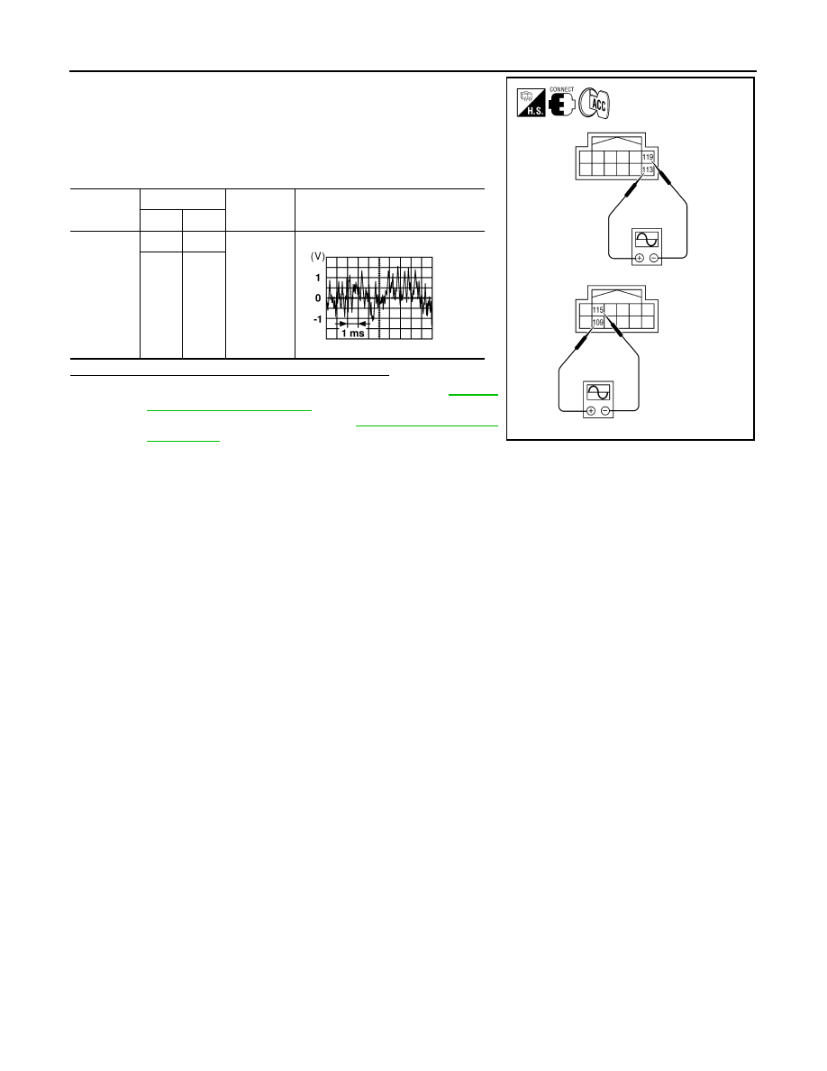
1. Connect AV control unit connector and BOSE speaker amp.
connector.
2. Turn ignition switch to ACC.
3. Push POWER switch.
4. Check the signal between AV control unit harness connector ter-
minals with CONSULT or oscilloscope.
Are the audio signal voltage readings as specified?
YES
>> Replace BOSE speaker amp. Refer to
.
NO
>> Replace AV control unit. Refer to
Connector
Terminals
Condition
Reference
signal
(+)
(-)
M157
113
119
Receive
audio sig-
nal
109
115
AWNIA1981ZZ
SKIA0177E