Nissan Maxima. Manual - part 145
AV-400
< DTC/CIRCUIT DIAGNOSIS >
[COLOR DISPLAY - W/ BOSE]
RGB SYNCHRONIZING SIGNAL CIRCUIT
RGB SYNCHRONIZING SIGNAL CIRCUIT
Description
INFOID:0000000009471356
Transmit the RGB synchronizing signal to the display unit so as to synchronize the RGB image displayed with
AV control unit.
Diagnosis Procedure
INFOID:0000000009471357
Regarding Wiring Diagram information, refer to
AV-449, "Wiring Diagram - With BOSE Audio system Without
1.
CHECK CONTINUITY RGB SYNCHRONIZING SIGNAL CIRCUIT
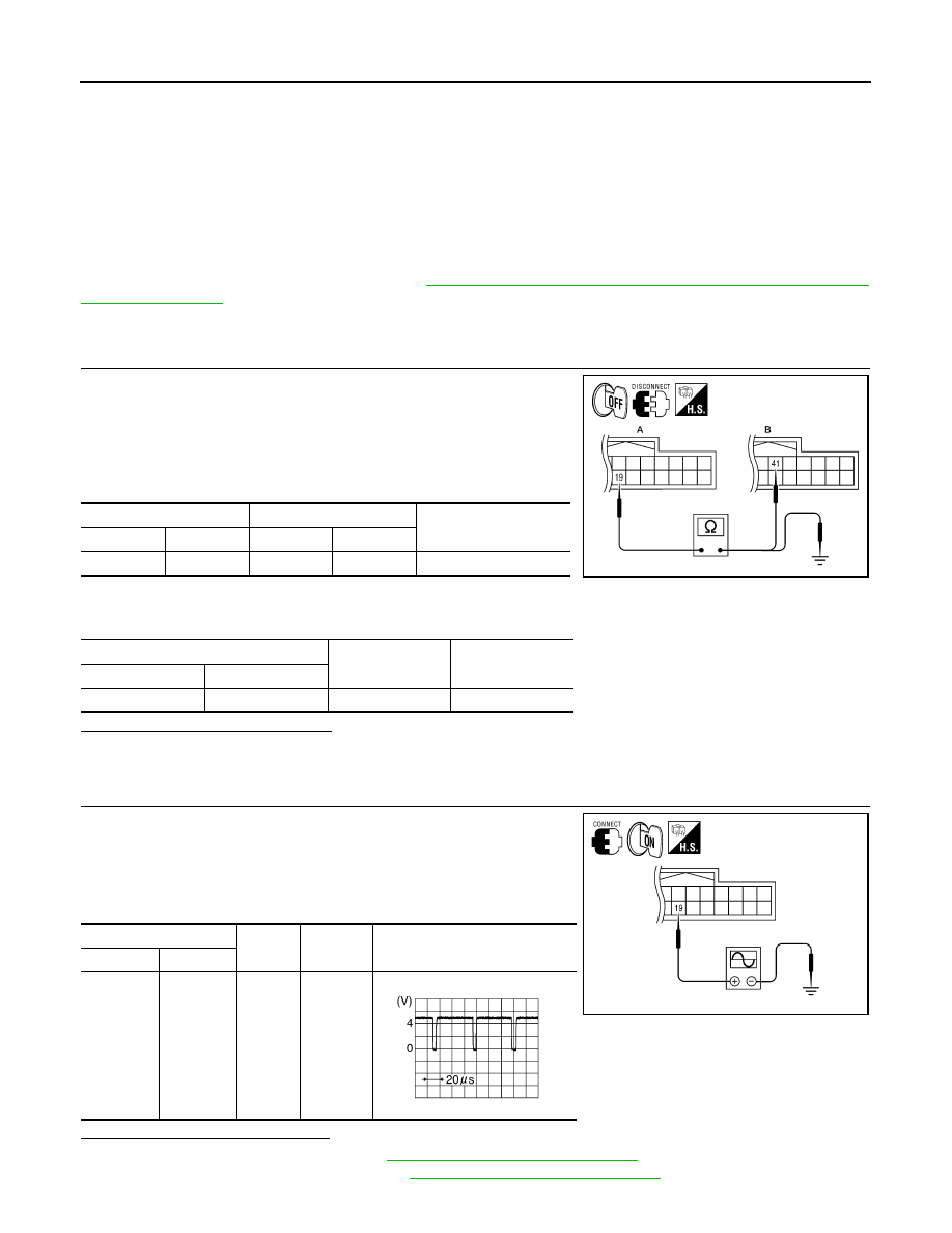
1. Turn ignition switch OFF.
2. Disconnect display unit connector M141 and AV control unit con-
nector M154.
3. Check continuity between display unit harness connector M141
(A) terminal 19 and AV control unit harness connector M154 (B)
terminal 41.
4. Check continuity between display unit harness connector M141
(A) terminal 19 and ground.
Are continuity results as specified?
YES
>> GO TO 2.
NO
>> Repair harness or connector.
2.
CHECK RGB SYNCHRONIZING SIGNAL
1. Connect display unit connector M141 and AV control unit con-
nector M154.
2. Turn ignition switch ON.
3. Check signal between display unit harness connector M141 ter-
minal 19 and ground.
Are voltage readings as specified?
YES
>> Replace display unit. Refer to
AV-484, "Removal and Installation"
NO
>> Replace AV control unit. Refer to
AV-481, "Removal and Installation"
.
A
B
Continuity
Connector
Terminal
Connector
Terminal
M141
19
M154
41
Yes
A
—
Continuity
Connector
Terminal
M141
19
Ground
No
ALNIA0388GB
(+)
(-)
Condition
Reference signal
Connector
Terminal
M141
19
Ground
Receive
audio sig-
nal
ALNIA0389GB
SKIB3603E