Nissan Maxima. Manual - part 143
AV-392
< DTC/CIRCUIT DIAGNOSIS >
[COLOR DISPLAY - W/ BOSE]
POWER SUPPLY AND GROUND CIRCUIT
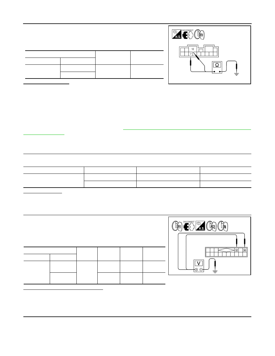
1. Turn ignition switch OFF.
2. Disconnect BOSE speaker amp. connector.
3. Check continuity between BOSE speaker amp. harness connec-
tor B110 terminal 7,12 and ground.
Does continuity exist?
YES
>> Inspection End.
NO
>> Repair harness or connector.
SATELLITE RADIO TUNER
SATELLITE RADIO TUNER : Diagnosis Procedure
INFOID:0000000009471346
Regarding Wiring Diagram information, refer to
AV-449, "Wiring Diagram - With BOSE Audio system Without
1.
CHECK FUSES
Check that the following fuses of the satellite radio tuner (factory installed) are not blown.
Are the fuses OK?
YES
>> GO TO 2.
NO
>> If fuse is blown, be sure to eliminate cause of malfunction before installing new fuse.
2.
POWER SUPPLY CIRCUIT CHECK
1. Turn ignition switch OFF.
2. Disconnect satellite radio tuner (factory installed) connector
B111.
3. Check voltage between the satellite radio tuner (factory
installed) and ground.
Are the voltage readings as specified?
YES
>> GO TO 3.
NO
>> • Check connector housings for disconnected or loose terminals.
• Repair harness or connector.
3.
GROUND CIRCUIT CHECK
(+)
(-)
Continuity
Connector
Terminal
B110
7
Ground
Yes
12
AWNIA1720ZZ
Unit
Terminals
Signal name
Fuse No.
Satellite radio tuner (factory in-
stalled)
32
Battery power
24
36
Ignition switch ACC or ON
17
(+)
(-)
OFF
ACC
ON
Connector
Terminal
B111
32
Ground
Battery
voltage
Battery
voltage
Battery
voltage
36
0V
Battery
voltage
Battery
voltage
WKIA4539E