Nissan Maxima. Manual - part 144


  Index      Nissan     Nissan Maxima (2009-2014 year) - Service and Repair Manual


Search            


Content   ..  142  143  144  145   ..


Nissan Maxima. Manual - part 144


AV-396

< DTC/CIRCUIT DIAGNOSIS >

[COLOR DISPLAY - W/ BOSE]

POWER SUPPLY AND GROUND CIRCUIT

NO

>> Repair harness or connector.

3.

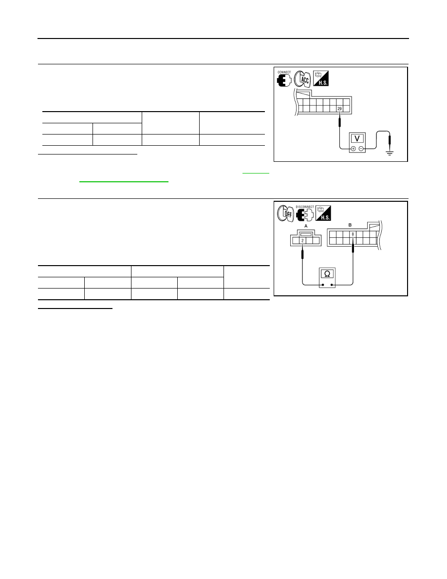
CHECK POWER SUPPLY CIRCUIT (BLUETOOTH

®

 CONTROL UNIT SIDE)

1. Connect Bluetooth

®

 control unit harness connector.

2. Turn ignition switch to ACC.
3. Check voltage between Bluetooth

®

 control unit harness connec-

tor B131 terminal 29 and ground.

Is approximately 5V present?

YES

>> Go to 4.

NO

>> Replace Bluetooth

®

 control unit. Refer to 

AV-503,

"Removal and Installation"

.

4.

CHECK GROUND CIRCUIT

1. Turn ignition switch OFF.
2. Disconnect microphone harness connector R7 and Bluetooth

®

control unit harness connector B131.

3. Check continuity between microphone harness connector R7

(A) terminal 2 and Bluetooth

®

 control unit harness connector

B131 (B) terminal 8. 

Does continuity exist?

YES

>> Inspection End.

NO

>> Repair harness or connector.

(+)

(-)

Value (Approx.)

Connector

Terminal

B131

29

Ground

5V

ALNIA0321GB

A

B

Continuity

Connector

Terminal

Connector

Terminal

R7

2

B131

8

Yes

ALNIA0322GB

AV

RGB (R: RED) SIGNAL CIRCUIT

AV-397

< DTC/CIRCUIT DIAGNOSIS >

[COLOR DISPLAY - W/ BOSE]

C

D

E

F

G

H

I

J

K

L

M

B

A

O

P

RGB (R: RED) SIGNAL CIRCUIT

Description

INFOID:0000000009471350

Transmit the image displayed with AV control unit with RGB signal to the display unit.

Diagnosis Procedure

INFOID:0000000009471351

Regarding Wiring Diagram information, refer to 

AV-449, "Wiring Diagram - With BOSE Audio system Without

Navigation System"

.

1.

CHECK CONTINUITY RGB (R: RED) SIGNAL CIRCUIT

1. Turn ignition switch OFF.

2. Disconnect display unit connector M141 and AV control unit con-

nector M154.

3. Check continuity between display unit harness connector M141

(A) terminal 17 and AV control unit harness connector M154 (B)

terminal 40.

4. Check continuity between display unit harness connector M141

(A) terminal 17 and ground.

Are the continuity results as specified?

YES

>> GO TO 2.

NO

>> Repair harness or connector.

2.

CHECK RGB (R: RED) SIGNAL

1. Connect display unit connector M141 and AV control unit con-

nector M154.

2. Turn ignition switch ON.

3. Check signal between display unit harness connector M141 ter-

minal 17 and ground.

Are the voltage readings as specified?

YES

>> Replace display unit. Refer to 

AV-484, "Removal and Installation"

.

NO

>> Replace AV control unit. Refer to 

AV-481, "Removal and Installation"

.

A

B

Continuity

Connector

Terminal

Connector

Terminal

M141

17

M154

40

Yes

A

Continuity

Connector

Terminal

M141

17

Ground

No

ALNIA0382GB

(+)

(-)

Condition

Reference signal

Connector

Terminal

M141

17

Ground

Receive 
audio sig-
nal

ALNIA0383GB

SKIB2238J

AV-398

< DTC/CIRCUIT DIAGNOSIS >

[COLOR DISPLAY - W/ BOSE]

RGB (G: GREEN) SIGNAL CIRCUIT

RGB (G: GREEN) SIGNAL CIRCUIT

Description

INFOID:0000000009471352

Transmit the image displayed with AV control unit with RGB signal to the display unit.

Diagnosis Procedure

INFOID:0000000009471353

Regarding Wiring Diagram information, refer to 

AV-449, "Wiring Diagram - With BOSE Audio system Without

Navigation System"

.

1.

CHECK CONTINUITY RGB (G: GREEN) SIGNAL CIRCUIT

1. Turn ignition switch OFF.

2. Disconnect display unit connector M141 and AV control unit con-

nector M154.

3. Check continuity between display unit harness connector M141

(A) terminal 6 and AV control unit harness connector M154 (B)

terminal 39.

4. Check continuity between display unit harness connector M141

(A) terminal 6 and ground.

Are the continuity results as specified?

YES

>> GO TO 2.

NO

>> Repair harness or connector.

2.

CHECK RGB (G: GREEN) SIGNAL

1. Connect display unit connector M141 and AV control unit con-

nector M154.

2. Turn ignition switch ON.

3. Check signal between display unit harness connector M141 ter-

minal 6 and ground.

Are voltage readings as specified?

YES

>> Replace display unit. Refer to 

AV-484, "Removal and Installation"

.

NO

>> Replace AV control unit. Refer to 

AV-481, "Removal and Installation"

.

A

B

Continuity

Connector

Terminal

Connector

Terminal

M141

6

M154

39

Yes

A

Continuity

Connector

Terminal

M141

6

Ground

No

ALNIA0384GB

(+)

(-)

Condition

Reference signal

Connector

Terminal

M141

6

Ground

Receive 
audio sig-
nal

ALNIA0385GB

SKIB2236J

AV

RGB (B: BLUE) SIGNAL CIRCUIT

AV-399

< DTC/CIRCUIT DIAGNOSIS >

[COLOR DISPLAY - W/ BOSE]

C

D

E

F

G

H

I

J

K

L

M

B

A

O

P

RGB (B: BLUE) SIGNAL CIRCUIT

Description

INFOID:0000000009471354

Transmit the image displayed with AV control unit with RGB signal to the display unit.

Diagnosis Procedure

INFOID:0000000009471355

Regarding Wiring Diagram information, refer to 

AV-449, "Wiring Diagram - With BOSE Audio system Without

Navigation System"

.

1.

CHECK CONTINUITY RGB (B: BLUE) SIGNAL CIRCUIT

1. Turn ignition switch OFF.

2. Disconnect display unit connector M141 and AV control unit con-

nector M154.

3. Check continuity between display unit harness connector M141

(A) terminal 18 and AV control unit harness connector M154 (B)

terminal 38.

4. Check continuity between display unit harness connector M141

(A) terminal 18 and ground.

Are continuity results as specified?

YES

>> GO TO 2.

NO

>> Repair harness or connector.

2.

CHECK RGB (B: BLUE) SIGNAL

1. Connect display unit connector M141 and AV control unit con-

nector M154.

2. Turn ignition switch ON.

3. Check signal between display unit harness connector M141 ter-

minal 18 and ground.

Are voltage readings as specified?

YES

>> Replace display unit. Refer to 

AV-484, "Removal and Installation"

.

NO

>> Replace AV control unit. Refer to 

AV-481, "Removal and Installation"

.

A

B

Continuity

Connector

Terminal

Connector

Terminal

M141

18

M154

38

Yes

A

Continuity

Connector

Terminal

M141

18

Ground

No

ALNIA0386GB

(+)

(-)

Condition

Reference signal

Connector

Terminal

M141

18

Ground

Receive 
audio sig-
nal

ALNIA0387GB

SKIB2237J


Content   ..  142  143  144  145   ..