Nissan Maxima. Manual - part 134
AV-356
< SYSTEM DESCRIPTION >
[COLOR DISPLAY - W/ BOSE]
DIAGNOSIS SYSTEM (AV CONTROL UNIT)
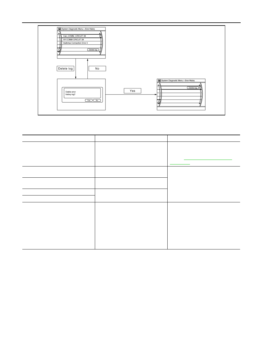
Error Item
Some error items may be displayed simultaneously according to the cause. If some error items are displayed
simultaneously, the detection of the cause can be performed by the combination of display items.
JSNIA0151GB
Error item
Description
Possible malfunction factor/Action to take
CAN COMM CIRCUIT
CAN communication malfunction is detect-
ed.
Perform diagnosis with CONSULT, and
then repair the malfunctioning parts accord-
ing to the diagnosis results.
Refer to
CONTROL UNIT (CAN)
CAN initial diagnosis malfunction is detect-
ed.
Replace the AV control unit.
CONTROL UNIT (AV)
AV communication circuit initial diagnosis
malfunction is detected.
FLASH-ROM Error Of Control Unit
AV control unit malfunction is detected.
CAN Controller Memory Error
Front Display Connection Error
When any one of the following items is de-
tected:
• front display unit power supply and
ground circuits are malfunctioning.
• serial communication circuits between
AV control unit and front display unit are
malfunctioning.
• serial communication signal between AV
control unit and front display unit is mal-
functioning.
• Front display unit power supply and
ground circuits.
• Serial communication circuits between
AV control unit and front display unit.