Nissan Maxima. Manual - part 135


  Index      Nissan     Nissan Maxima (2009-2014 year) - Service and Repair Manual


Search            


Content   ..  133  134  135  136   ..


Nissan Maxima. Manual - part 135


AV-360

< SYSTEM DESCRIPTION >

[COLOR DISPLAY - W/ BOSE]

DIAGNOSIS SYSTEM (AV CONTROL UNIT)

DATA MONITOR

ALL SIGNALS

• Displays the status of the following vehicle signals inputted into the AV control unit.

• For each signal, actual signal can be compared with the condition recognized on the system.

HDD CONN [U1218]

AV control unit malfunction is detected.

• If the hard disk drive (HDD) is function-

ing normally, there is a possibility of a 
temporary malfunction.

• Replace the AV control unit if the mal-

function occurs constantly.

HDD READ [U1219]

HDD WRITE [U121A]

HDD COMM [U121B]

HDD ACCESS [U121C]

USB CONTROLLER [U1225]

USB connection malfunction is detected.

Check that the connection to the USB con-
nector is normal.

DSP CONN [U121D]

AV control unit malfunction is detected.

• If a disc can be played, then there is a 

possibility of the detection of a tempo-
rary malfunction.

• Replace the AV control unit if the mal-

function occurs constantly.

DSP COMM [U121E]

DVD COMM [U1227]

AV control unit malfunction is detected.

• If DVD can be played, then there is a 

possibility of the detection of a tempo-
rary malfunction.

• Replace the AV control unit if the mal-

function occurs constantly.

CONFIG UNFINISH [U122A]

The writing of configuration data is incom-
plete.

Write configuration data with CONSULT.

ST ANGLE SEN CALIB [U1232]

Predictive course line center position ad-
justment of the steering angle sensor is in-
complete.

Adjust the predictive course line center po-
sition of the steering angle sensor.

FRONT DISP CONN [U1243]

When either one of the following items are 
detected:
• Display unit power supply and ground 

circuits malfunction is detected.

• Communication circuits between AV 

control unit and display unit.

• Display unit power supply and ground 

circuits.

• Communication circuits between AV 

control unit and AV display unit.

SAT CONN [U1255]

Satellite radio tuner malfunction is detect-
ed.

Replace the satellite radio tuner if the mal-
function occurs constantly.

USB OVERCURRENT [U1263]

Detection of over current in USB connect-
er.

Check USB harness between the AV con-
trol unit and USB connector.

• AV COMM CIRCUIT [U1300]
• SWITCH CONN [U1240]

When either one of the following items are 
detected:
• Multifunction switch power supply and 

ground circuits are malfunctioning.

• AV communication circuits between AV 

control unit and multifunction switch are 
malfunctioning.

• Multifunction switch power supply and 

ground circuits.

• AV communication circuits between AV 

control unit and multifunction switch.
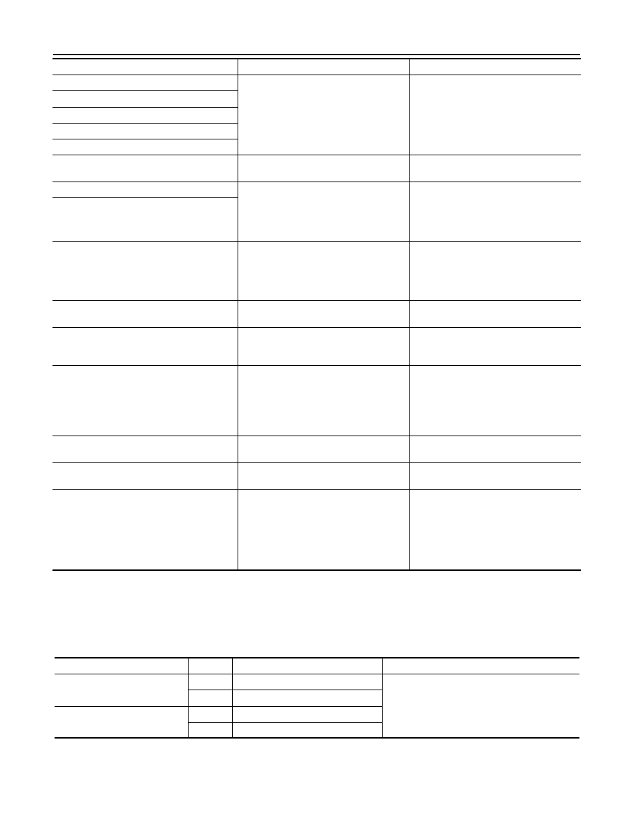
Error item

Description

Possible malfunction factor/Action to take

Display Item

Display

Vehicle status

Remarks

VHCL SPD SIG

On

Vehicle speed >0 km/h (0 MPH)

Changes in indication may be delayed. This is 
normal.

Off

Vehicle speed =0 km/h (0 MPH)

PKB SIG

On

Parking brake is applied.

Off

Parking brake is released.

AV

DIAGNOSIS SYSTEM (AV CONTROL UNIT)

AV-361

< SYSTEM DESCRIPTION >

[COLOR DISPLAY - W/ BOSE]

C

D

E

F

G

H

I

J

K

L

M

B

A

O

P

SELECTION FROM MENU

Allows the technician to select which vehicle signals should be displayed and displays the status of the

selected vehicle signals.

WORK SUPPORT

CONFIGURATION

Configuration has three functions as follows.

ILLUM SIG

On

Block the light beam from the auto 
light optical sensor when the light 
SW is ON.

Off

Expose the auto light optical sensor 
to light when the light SW is OFF or 
ON.

IGN SIG

On

Ignition switch ON

Off

Ignition switch in ACC position

REV SIG

On

Selector lever in R position

Changes in indication may be delayed. This is 
normal.

Off

Selector lever in any position other 
than R

Display Item

Display

Vehicle status

Remarks

Item to be selected

Description

VHCL SPD SIG

The same as when “ALL SIGNALS” is selected.

PKB SIG

ILLUM SIG

IGN SIG

REV SIG

Conditions

Description

ST ANGLE SENSOR ADJUSTMENT

Steering angle sensor neutral position adjustment can be per-
formed. Refer to 

BRC-6, "ADJUSTMENT OF STEERING ANGLE 

SENSOR NEUTRAL POSITION : Description"

.

Function

Description

READ CONFIGURATION

• Reads the vehicle configuration of current AV control unit.
• Saves the read vehicle configuration.

WRITE CONFIGURATION-Manual selection

Writes the vehicle configuration with manual selection.

WRITE CONFIGURATION-Config file

Writes the vehicle configuration with saved data.

AV-362

< SYSTEM DESCRIPTION >

[COLOR DISPLAY - W/ BOSE]

DIAGNOSIS SYSTEM (BLUETOOTH® CONTROL UNIT)

DIAGNOSIS SYSTEM (BLUETOOTH® CONTROL UNIT)

Diagnosis Description

INFOID:0000000009471300

The Bluetooth

®

 control unit has two diagnostic checks. The first diagnostic check is performed automatically

every ignition cycle during control unit initialization. The second diagnostic check is performed by the techni-

cian using the steering wheel audio control switches prior to trouble diagnosis.

BLUETOOTH

®

 CONTROL UNIT INITIALIZATION CHECKS

• Internal control unit failure
• Bluetooth

®

 antenna connection open or shorted

• Steering wheel audio control switches [

 (PHONE/SEND),   (PHONE/END)] stuck closed

• Vehicle speed pulse count

• Microphone connection test (with playback to operator)
• Bluetooth

®

 inquiry check

OPERATION PROCEDURE

1. Turn ignition switch to ACC or ON.
2. Wait for the Bluetooth

®

 system to complete initialization. This may take up to 20 seconds.

3. Press and hold the steering wheel audio control switch 

(PHONE/SEND) button for at least 5 seconds. The Bluetooth

®

system will begin to play a verbal prompt.

4. While the prompt is playing, press and hold the steering wheel

audio control switch 

 (PHONE/END) button until you hear the

“Diagnostics mode” prompt. The Bluetooth

®

 system will sound a

5-second beep.

5. While the beep is sounding, press and hold the steering wheel

audio control switch 

 (PHONE/END) button again until you

hear prompts.

6. The Bluetooth

®

 system has now entered into the diagnostic

mode. Results of the diagnostic checks will be verbalized to the

technician. Refer to 

AV-362, "Work Flow"

.

7. After the failure records are reported, an interactive microphone

test will be performed. Follow the voice prompt. If the micro-

phone test fails, refer to 

AV-362, "Work Flow"

.

Work Flow

INFOID:0000000009471301

AWNIA1979ZZ

AWNIA1980ZZ

Failure Message

Action

“Internal failure”

Replace Bluetooth

®

 control unit. Refer to 

AV-503, "Removal and Installation"

“Bluetooth

®

 antenna open”

1.

Inspect harness connection.

2.

Replace Bluetooth

®

 antenna. Refer to 

AV-502, "Removal and Installation"

.

“Bluetooth

®

 antenna shorted”

“Phone/Send for Hands Free System is stuck”

Check steering wheel audio control switches. Refer to 

AV-496, "Removal and In-

stallation"

.

“Phone/End for the Hands Free System is stuck”

“Microphone test” (failed interactive test)

1.

Inspect harness between Bluetooth

®

 control unit and microphone.

2.

Replace microphone. Refer to 

AV-501, "Removal and Installation"

 .

AV

U1000 CAN COMM CIRCUIT

AV-363

< DTC/CIRCUIT DIAGNOSIS >

[COLOR DISPLAY - W/ BOSE]

C

D

E

F

G

H

I

J

K

L

M

B

A

O

P

DTC/CIRCUIT DIAGNOSIS

U1000 CAN COMM CIRCUIT

Description

INFOID:0000000009471302

CAN (Controller Area Network) is a serial communication line for real time application. It is an on-vehicle mul-

tiplex communication line with high data communication speed and excellent error detection ability. Many elec-

tronic control units are equipped on a vehicle and each control unit shares information and links with other

control units during operation (not independent). In CAN communication, control units are connected with 2

communication lines (CAN-H, CAN-L) allowing a high rate of information transmission with less wiring. Each

control unit transmits/receives data but selectively reads required data only.

DTC Logic

INFOID:0000000009471303

DTC DETECTION LOGIC

Diagnosis Procedure

INFOID:0000000009471304

1.

PERFORM SELF DIAGNOSTIC

1. Turn ignition switch ON and wait for 2 seconds or more.

2. Check “Self Diagnostic Result” of “AV Control Unit”. 
Is “CAN COMM CIRCUIT” displayed?

YES

>> Refer to “LAN system”. Refer to 

LAN-15, "Trouble Diagnosis Flow Chart"

.

NO

>> Refer to GI section. Refer to 

GI-41, "Intermittent Incident"

.

DTC

Display contents of CON-

SULT

Diagnostic item is detected when ...

Probable malfunction location

U1000

CAN COMM CIRCUIT

When AV control unit is not transmitting or re-
ceiving CAN communication signal for 2 sec-
onds or more.

CAN communication system.


Content   ..  133  134  135  136   ..