Content .. 1163 1164 1165 1166 ..
Nissan Maxima. Manual - part 1165
TM-124
< ECU DIAGNOSIS INFORMATION >
[CVT: RE0F09B]
TCM
If an unexpected signal is sent from the CVT fluid temperature sensor to the TCM, the gear ratio in use before
receiving the unexpected signal is maintained or the gear ratio is controlled to keep engine speed under 5,000
rpm.
Secondary Pressure Sensor
• If an unexpected signal is sent from the secondary pressure sensor to the TCM, the secondary pressure
feedback control is stopped and the offset value obtained before the non-standard condition occurs is used
to control line pressure.
• If secondary pressure sensor error signal is inputted to the TCM, secondary pressure feedback control
stops, but line pressure is controlled normally.
Line Pressure Solenoid Valve
If an unexpected signal is sent from the solenoid valve to the TCM, the line pressure solenoid valve is turned
OFF to achieve the maximum fluid pressure.
Secondary Pressure Solenoid Valve
If an unexpected signal is sent from the solenoid valve to the TCM, the secondary pressure solenoid valve is
turned OFF to achieve the maximum fluid pressure.
Torque Converter Clutch Solenoid Valve
If an unexpected signal is sent from the solenoid valve to the TCM, the torque converter clutch solenoid valve
is turned OFF to cancel the lock-up.
Step Motor
If an unexpected signal is sent from the step motor to the TCM, the step motor coil phases “A” through “D” are
all turned OFF to hold the gear ratio used just before the non-standard condition occurred.
Lock-up Select Solenoid Valve
If an unexpected signal is sent from the solenoid valve to the TCM, the lock-up select solenoid valve is turned
OFF to cancel the lock-up.
TCM Power Supply (Memory Back-up)
Transaxle assembly is protected by limiting the engine torque when the memory back-up power supply (for
controlling) from the battery is not supplied to the TCM. Normal status is restored when turning the ignition
switch OFF to ON after the normal power supply.
DTC Inspection Priority Chart
INFOID:0000000010113946
If some DTCs are displayed at the same time, perform inspections one by one based on the following priority
chart.
NOTE:
If DTC “U0100/U1000/U1010/P1709” is indicated with other DTCs, start from a diagnosis for DTC
“U0100/U1000/U1010/P1709”. Refer to
(U1000),
(P1709).
DTC Index
INFOID:0000000010113947
NOTE:
If DTC “U0100/U1000/U1010/P1709” is indicated with other DTCs, start from a diagnosis for DTC
“U0100/U1000/U1010/P1709”. Refer to
(U1000),
(P1709).
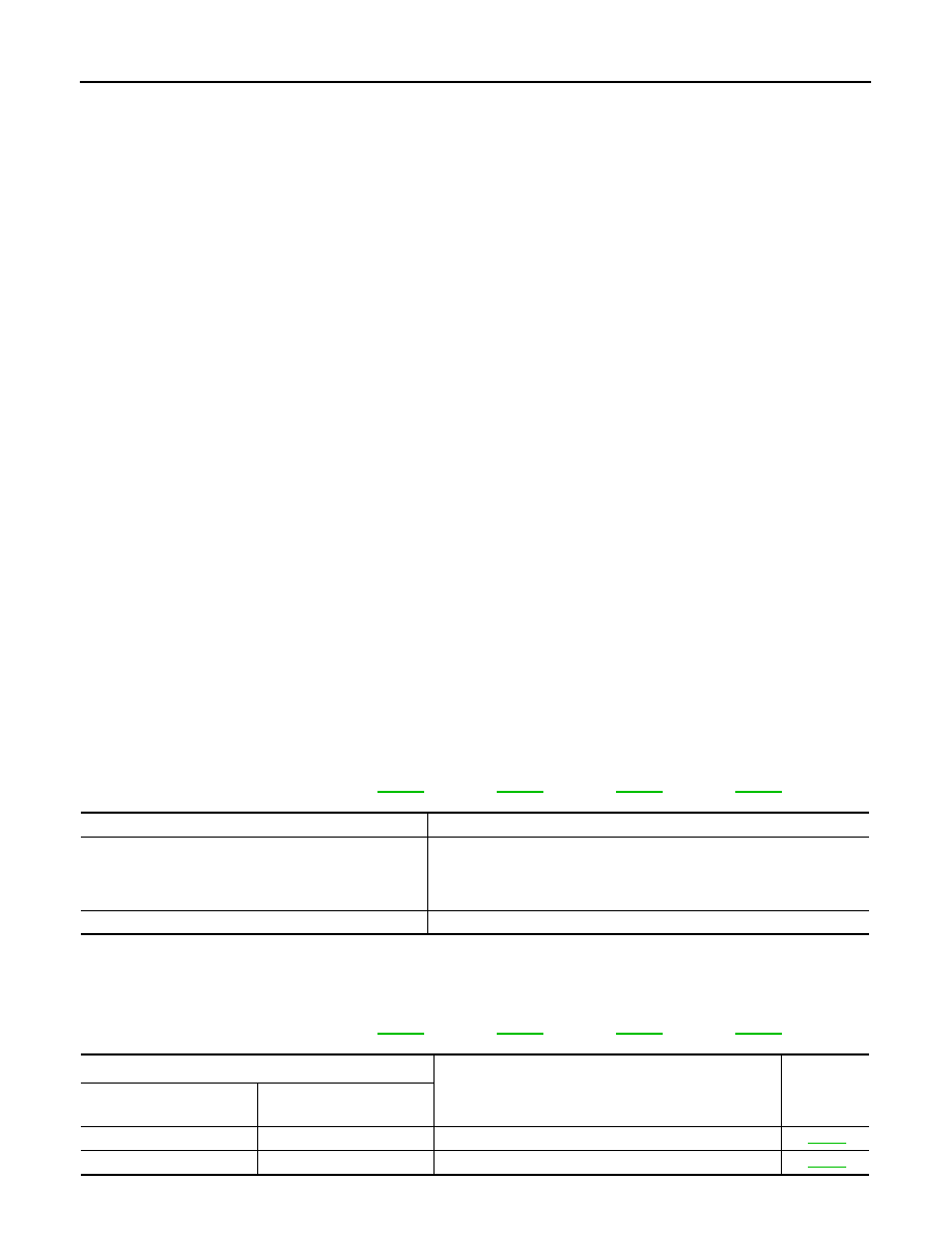
Priority
Detected items (DTC)
1
• U0100
• U1000
• U1010
• P1709
2
Except above
DTC
*1
Items
(CONSULT screen terms)
Reference
“TRANSMISSION” with
CONSULT
MIL
*2
, “ENGINE” with CON-
SULT or GST
P0615
—
STARTER RELAY
P0703
—
BRAKE SWITCH B