Nissan Maxima. Manual - part 1163


  Index      Nissan     Nissan Maxima (2009-2014 year) - Service and Repair Manual


Search            


Content   ..  1161  1162  1163  1164   ..


Nissan Maxima. Manual - part 1163


TM-116

< DTC/CIRCUIT DIAGNOSIS >

[CVT: RE0F09B]

SHIFT LOCK SYSTEM

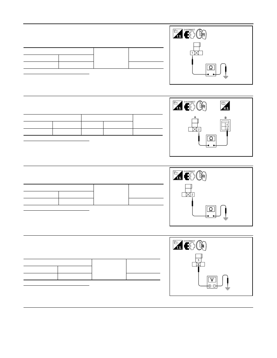
1. Remove shift lock relay.

2. Check continuity between shift lock relay connector E27 termi-

nal 1 and ground.

Is the inspection result normal?

YES

>> GO TO 4.

NO

>> Repair or replace damaged parts.

4.

CHECK HARNESS BETWEEN SHIFT LOCK RELAY AND STOP LAMP SWITCH FOR OPEN

Check continuity between shift lock relay connector E27 (A) terminal

2 and stop lamp switch connector E38 (B) terminal 4.

Is the inspection result normal?

YES

>> GO TO 5.

NO

>> Repair or replace damaged parts.

5.

CHECK HARNESS BETWEEN SHIFT LOCK RELAY AND STOP LAMP SWITCH FOR SHORT CIRCUIT

Check continuity between shift lock relay connector E27 terminal 2

and ground.

Is the inspection result normal?

YES

>> GO TO 6.

NO

>> Repair or replace damaged parts.

6.

CHECK POWER SOURCE (SHIFT LOCK RELAY)

1. Turn ignition switch ON.

2. Check voltage between shift lock relay connector E27 terminal 5

and ground.

Is the inspection result normal?

YES

>> GO TO 9.

NO

>> GO TO 7.

7.

CHECK HARNESS BETWEEN FUSE BLOCK (J/B) AND SHIFT LOCK RELAY FOR OPEN

1. Turn ignition switch OFF.

Shift lock relay

Ground

Continuity

Connector

Terminal (+)

E27

1

Yes

AWDIA0586ZZ

Shift lock relay

stop lamp switch

Continuity

Connector

Terminal

Connector

Terminal

E27 (A)

2

E38 (B)

4

Yes

AWDIA0587ZZ

Shift lock relay

Ground

Continuity

Connector

Terminal

E27

2

No

AWDIA0588ZZ

Shift lock relay

Ground

Voltage (Approx.)

Connector

Terminal

E27

5

Battery voltage

AWDIA0589ZZ

SHIFT LOCK SYSTEM

TM-117

< DTC/CIRCUIT DIAGNOSIS >

[CVT: RE0F09B]

C

E

F

G

H

I

J

K

L

M

A

B

TM

N

O

P

2. Disconnect fuse block (J/B).

3. Check continuity between fuse block (J/B) connector E6 (A) ter-

minal 4P and shift lock relay connector E27 (B) terminal 5.

Is the inspection result normal?

YES

>> GO TO 8.

NO

>> Repair or replace damaged parts.

8.

CHECK HARNESS BETWEEN FUSE BLOCK (J/B) AND SHIFT LOCK RELAY FOR SHORT CIRCUIT

Check continuity between shift lock relay connector E27 terminal 5

and ground.

Is the inspection result normal?

YES

>> Check the following. If NG, repair or replace damaged

parts.

• 10A (No. 3, located in fuse block [J/B])

• Ignition switch

NO

>> Repair or replace damaged parts.

9.

CHECK HARNESS BETWEEN SHIFT LOCK RELAY AND CVT SHIFT SELECTOR FOR OPEN

1. Disconnect CVT shift selector connector.

2. Check continuity between shift lock relay connector E27 (A) ter-

minal 3 and CVT shift selector connector M78 (B) terminal 6.

Is the inspection result normal?

YES

>> GO TO 10.

NO

>> Repair or replace damaged parts.

10.

CHECK HARNESS BETWEEN SHIFT LOCK RELAY AND CVT SHIFT SELECTOR FOR SHORT CIR-

CUIT

Check continuity between shift lock relay connector E27 terminal 3

and ground.

Is the inspection result normal?

YES

>> GO TO 11.

NO

>> Repair or replace damaged parts.

11.

CHECK SHIFT LOCK RELAY

Check shift lock relay. Refer to 

TM-118, "Component Inspection (Shift Lock Relay)"

.

Is the inspection result normal?

YES

>> GO TO 12.

Fuse block (J/B)

Shift lock relay

Continuity

Connector

Terminal

Connector

Terminal

E6 (A)

4P

E27 (B)

5

Yes

AWDIA0590ZZ

Shift lock relay

Ground

Continuity

Connector

Terminal

E27

5

No

AWDIA0591ZZ

Shift lock relay

CVT shift selector

Continuity

Connector

Terminal

Connector

Terminal

E27 (A)

3

M78 (B)

6

Yes

AWDIA0592ZZ

Shift lock relay

Ground

Continuity

Connector

Terminal

E27

3

No

AWDIA0593ZZ

TM-118

< DTC/CIRCUIT DIAGNOSIS >

[CVT: RE0F09B]

SHIFT LOCK SYSTEM

NO

>> Replace shift lock relay.

12.

CHECK GROUND CIRCUIT (CVT SHIFT SELECTOR)

Check continuity between CVT shift selector connector M78 terminal

7 and ground.

Is the inspection result normal?

YES

>> Replace shift lock solenoid. Refer to 

TM-170, "Exploded

View"

.

NO

>> Repair or replace damaged parts.

Component Inspection (Stop Lamp Switch)

INFOID:0000000009469165

1.

CHECK STOP LAMP SWITCH

Check continuity between stop lamp switch terminals.

Is the inspection result normal?

YES

>> Inspection End

NO

>> Replace stop lamp switch. Refer to 

BR-18, "Exploded

View"

.

Component Inspection (Shift Lock Relay)

INFOID:0000000009469166

1.

CHECK SHIFT LOCK RELAY

1. Apply battery voltage between terminals 2 and 1 of the shift lock

relay.

CAUTION:

Connect a fuse between the terminals when applying bat-

tery voltage.

2. Check continuity between shift lock relay terminals 5 and 3.

Is the inspection result normal?

YES

>> Inspection End

NO

>> Replace shift lock relay.

CVT shift selector

Ground

Continuity

Connector

Terminal

M78

7

Yes

AWDIA0594ZZ

Stop lamp switch terminals

Condition

Continuity

3

4

Brake pedal depressed

Yes

Brake pedal released

No

AWDIA0419ZZ

Shift lock relay terminals

Condition

Continuity

5 and 3

Battery voltage applied between 
terminals 2 and 1.

Yes

WJIA0973E

TCM

TM-119

< ECU DIAGNOSIS INFORMATION >

[CVT: RE0F09B]

C

E

F

G

H

I

J

K

L

M

A

B

TM

N

O

P

ECU DIAGNOSIS INFORMATION

TCM

Reference Value

INFOID:0000000010113944

VALUES ON THE DIAGNOSIS TOOL

Item name

Condition 

Display value (Approx.)

VSP SENSOR

During driving

Approximately matches the speedometer 
reading.

ESTM VSP SIG

During driving

Approximately matches the speedometer 
reading.

PRI SPEED SEN

During driving (lock-up ON)

Approximately matches the engine speed.

ENG SPEED SIG

Engine running

Closely matches the tachometer reading.

SEC HYDR SEN 

“N” position idle

0.5 – 0.8 V

PRI HYDR SEN 

“N” position idle

1.0 – 1.5 V

ATFTEMP COUNT

*1

When CVT fluid temperature is 20

°C (68°F).

47

When CVT fluid temperature is 80

°C (176°F).

161

VIGN SEN

Ignition switch: ON

Battery voltage

VEHICLE SPEED

During driving

Approximately matches the speedometer 
reading.

PRI SPEED

During driving (lock-up ON)

Approximately matches the engine speed.

SEC SPEED

During driving

45 X Approximately matches the speedom-
eter reading.

ENG SPEED

Engine running

Closely matches the tachometer reading.

GEAR RATIO

During driving

2.37 – 0.43

ACC PEDAL OPEN

Released accelerator pedal - Fully depressed acceler-
ator pedal

0.0/8 – 8.0/8

SEC PRESS

“N” position idle

0.5 – 0.9 MPa

PRI PRESS

“N” position idle

0.3 – 0.9 MPa

STM STEP

During driving

−20 step – 190 step

ISOLT1

Lock-up OFF

0.0 A

Lock-up ON

0.7 A

ISOLT2

Release your foot from the accelerator pedal

0.8 A

Press the accelerator pedal all the way down

0.0 A

ISOLT3

Secondary pressure low - Secondary pressure high.

0.8 – 0.0 A

SOLMON1

Lock-up OFF

0.0 A

Lock-up ON

0.6 – 0.7 A

SOLMON2

“N” position idle

0.8 A

When stalled

0.3 – 0.6 A

SOLMON3

“N” position idle

0.6 – 0.7 A

When stalled

0.4 – 0.6 A

RANGE SW 3M

Selector lever in “D” position

On

Selector lever in “P”, “R” and “N” positions

Off

RANGE SW 4

Selector lever in “R” and “D” positions

On

Selector lever in “P” and “N” positions

Off

RANGE SW 3

Selector lever in “D” position

On

Selector lever in “P”, “R” and “N” positions

Off


Content   ..  1161  1162  1163  1164   ..