Nissan Maxima. Manual - part 1026


  Index      Nissan     Nissan Maxima (2009-2014 year) - Service and Repair Manual


Search            


Content   ..  1024  1025  1026  1027   ..


Nissan Maxima. Manual - part 1026


FRONT SEAT

SE-77

< UNIT DISASSEMBLY AND ASSEMBLY >

[WITH CLIMATE CONTROLLED SEATS]

C

D

E

F

G

H

I

K

L

M

A

B

SE

N

O

P

DRIVER SIDE : Disassembly and Assembly

INFOID:0000000009468152

SEAT ASSEMBLY WITH SIDE AIR BAG MODULE

WARNING:

Do not leave any objects (screwdriver, tools, etc.) on the seat during seatback repair. It can lead to per-

sonal injury if the side air bag should accidentally deploy.

CAUTION:

• Before servicing, turn the ignition switch OFF, disconnect both battery terminals and wait at least

three minutes.

• Handle the side air bag module carefully. During disassembly, always hold the side air bag module,

do not let it hang by the wire harness.

• Always place side air bag module with the stud bolt side facing downward.

• Always work from the side or back of the seatback assembly, do not work in front of the seat.

• Do not use air tools or electric tools when servicing the seat assembly.

• Replace the side air bag module if it has been dropped or sustained an impact.

• Do not insert any objects into the side air bag module.

• Do not disassemble the side air bag module.

• Do not expose the side air bag module to temperatures exceeding 93

°C (200°F).

• Do not expose the side air bag module to any oil, grease or water.

• During disassembly, do not damage the trim cover, chutes, connectors, retainers, clips, module har-

ness or the side air bag module.

NOTE:

• If the vehicle has been involved in a collision and the side air bag has deployed, the front seatback assembly

must be replaced.

• For side air bag module removal and installation, refer to 

SR-21, "Removal and Installation"

.

Disassembly

1. Remove the front seat assembly. Refer to 

SE-68, "Removal and Installation"

.

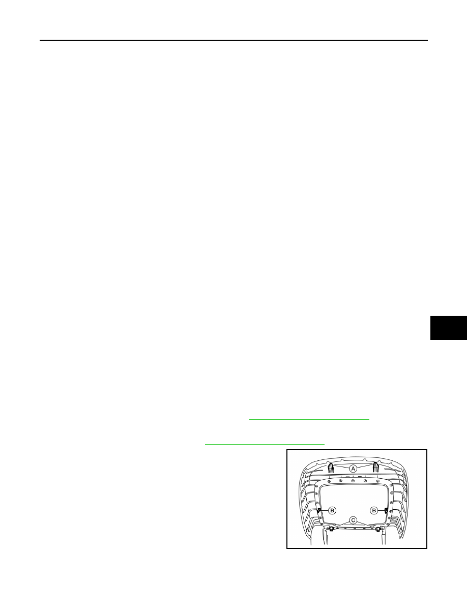
2. Remove the seatback board as follows: 

NOTE:

The seatback board is attached to the seat frame with the follow-

ing:

• Two top hooks (A)

• Two side hooks (B)

• Two bottom retainers (C)

10. Seat cushion trim

11. Seat cushion pad

12. Thigh extension tether

13. Thigh extension assembly

14. Climate controlled seat control unit 15. Seat cushion front finisher

16. Front slide cover

17. Clip

18. Power seat control unit

19. Seat cushion thermal electric device 

(TED) 

20. Lower seat duct

21. Climate controlled seat blower fil-

ter

22. Climate controlled seat blower motor 

assembly

23. Seat frame assembly

24. Rear slide cover

25. Power seat switch

26. Seat slide and lifter switch knob

27. Seat recline knob

28. Lumbar support switch

29. Seat cushion outer finisher (LH)

30. Recline device outer cover

31. Seat cushion inner finisher inside 

(LH)

32. Seatback assembly

33. Side air bag module

34. Seatback thermal electric device 

(TED)

35. Upper seat duct

36. Headrest holder (locked)

37. Headrest holder (free)

38. Seatback frame

39. Seatback trim 

40. Seatback pad

41. Headrest

42. Chute rod

ALJIA0587ZZ

SE-78

< UNIT DISASSEMBLY AND ASSEMBLY >

[WITH CLIMATE CONTROLLED SEATS]

FRONT SEAT

a. From the bottom of the seat, unhook the two seat skirt hooks as

shown.

b. Carefully pull upward on the lower seatback board to release the

two bottom retainers (C).

CAUTION:

Do not pull outward at two top hooks (A)

c.

Hold the seatback board at the side hook locations (B) and push

in the side hooks to release them from the seatback frame, then

pull it rearward.

d. Carefully pull the seatback board downward to disengage the

top hooks as shown.

CAUTION:

Use care not to break the seatback board hooks and retain-

ers. Replace seatback board if any hooks or retainers are

damaged.

3. Disconnect the upper seat duct.
4. Remove and discard the two chute rod bolts (A), then remove

the chute rod (1).

CAUTION:

Do not reuse the chute rod bolts.

ALJIA0588ZZ

ALJIA0587ZZ

ALJIA0589ZZ

Chute rod bolts (A)

: 8.2 N·m (0.84 kg-m, 73 in-lb)

ALJIA0590ZZ

FRONT SEAT

SE-79

< UNIT DISASSEMBLY AND ASSEMBLY >

[WITH CLIMATE CONTROLLED SEATS]

C

D

E

F

G

H

I

K

L

M

A

B

SE

N

O

P

5. Release the seven seatback retainers from the seatback frame

as shown. 

6. Reach in from the bottom of the seatback to release the guide

clips on the headrest holder. Squeeze the clips at the bottom

and push upward to remove as shown.

7. Push the seatback trim and seatback pad forward at the bottom

(1), then holding the seatback assembly on both sides, lift

upward (2). Remove the seatback trim and seatback pad as an

assembly from the seatback frame. 

ALJIA0598ZZ

PIIB4084J

ALJIA0599ZZ

SE-80

< UNIT DISASSEMBLY AND ASSEMBLY >

[WITH CLIMATE CONTROLLED SEATS]

FRONT SEAT

8. If required, separate the seatback trim from the seatback pad as

follows:

NOTE:

The seatback trim is attached to the seatback pad with the fol-

lowing:

• Five top hog rings (A)

• Four side hog rings (B)

• Three middle hog rings (C)

• Three bottom velcro fasteners (D)

a. Pull the seatback trim from the seatback pad to detach the vel-

cro fasteners.

b. Position the seatback trim to access the middle hog rings.

Remove the middle and side hog rings.

c.

Remove the top hog rings, then separate the seatback trim from

the seatback pad.

Assembly

Assembly is in the reverse order of disassembly. During assembly, note the following.

• When installing the seatback trim, firmly push down while sliding

your hand along the seams as shown (arrow) to ensure the velcro

fasteners are fastened properly.

• Make sure the chute rod is properly positioned and installed as shown.

: Front

ALJIA0594ZZ

ALJIA0656ZZ

ALJIA0654ZZ


Content   ..  1024  1025  1026  1027   ..