Nissan Maxima. Manual - part 20


  Index      Nissan     Nissan Maxima (2009-2014 year) - Service and Repair Manual


Search            


Content   ..  18  19  20  21   ..


Nissan Maxima. Manual - part 20


ADP-72

< DTC/CIRCUIT DIAGNOSIS >

FRONT DOOR SWITCH (DRIVER SIDE)

FRONT DOOR SWITCH (DRIVER SIDE)

Description

INFOID:0000000010051769

Detects front door LH open/close condition.

Component Function Check

INFOID:0000000010051770

1.

 CHECK FUNCTION

1. Select “DOOR SW-FL” in “DATA MONITOR” mode with CONSULT. 

2. Check the front door switch signal under the following conditions.

Is the indication normal?

YES

>> Inspection End.

NO

>> Perform diagnosis procedure. Refer to 

ADP-72, "Diagnosis Procedure"

.

Diagnosis Procedure

INFOID:0000000010051771

Regarding Wiring Diagram information, refer to 

ADP-150, "Wiring Diagram"

.

1.

 CHECK FRONT DOOR SWITCH LH CIRCUIT 

1. Turn ignition switch OFF.

2. Disconnect BCM.

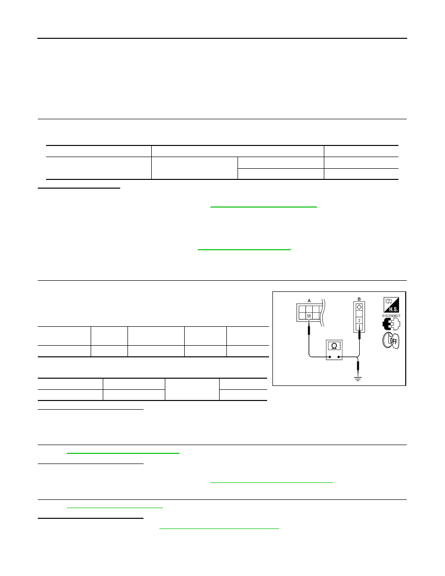
3. Check continuity between BCM connector and front door switch

LH connector.

4. Check continuity between BCM connector and ground.

Is the inspection result normal?

YES

>> GO TO 2

NO

>> Repair or replace harness.

2.

 CHECK FRONT DOOR SWITCH LH 

Refer to 

ADP-73, "Component Inspection"

.

Is the inspection result normal?

YES

>> GO TO 3

NO

>> Replace front door switch LH. Refer to 

DLK-230, "Removal and Installation"

.

3.

 CHECK INTERMITTENT INCIDENT

Refer to 

GI-41, "Intermittent Incident"

.

Is the inspection result normal?

YES

>> Replace BCM. Refer to 

BCS-79, "Removal and Installation"

.

NO

>> Repair or replace the malfunctioning part.

Monitor item

Condition

Status

DOOR SW-FL

Front door switch LH

Open

ON

Close

OFF

BCM connector

Terminal

Front door switch 

LH connector

Terminal

Continuity 

M18 (A)

58

B8 (B)

2

Yes

BCM connector

Terminal

Ground

Continuity 

M18 (A)

58

No

ALJIA0402ZZ

FRONT DOOR SWITCH (DRIVER SIDE)

ADP-73

< DTC/CIRCUIT DIAGNOSIS >

C

D

E

F

G

H

I

K

L

M

A

B

ADP

N

O

P

Component Inspection

INFOID:0000000010051772

1.

 CHECK FRONT DOOR SWITCH LH

1. Turn ignition switch OFF.

2. Disconnect front door switch LH.

3. Check continuity between front door switch LH terminals.

Is the inspection result normal?

YES

>> Inspection End.

NO

>> Replace front door switch LH. Refer to 

DLK-230, "Removal and Installation"

.

Terminal

Condition

Continuity

Front door switch LH

2

Ground part of 

door switch

Front door switch 
LH

Pushed

No

Released

Yes

LIIA2377E

ADP-74

< DTC/CIRCUIT DIAGNOSIS >

SLIDING SENSOR

SLIDING SENSOR

Description

INFOID:0000000010051773

• The sliding sensor is installed to the seat frame.

• The pulse signal is input to the driver seat control unit when sliding is performed.

• The driver seat control unit counts the pulse and calculates the sliding amount of the seat.

Component Function Check

INFOID:0000000010051774

1.

 CHECK FUNCTION

1. Select “SLIDE PULSE” in “DATA MONITOR” mode with CONSULT. 

2. Check sliding sensor switch signal under the following conditions.

Is the indication normal?

YES

>> Inspection End.

NO

>> Perform diagnosis procedure. Refer to 

ADP-74, "Diagnosis Procedure"

.

Diagnosis Procedure

INFOID:0000000010051775

Regarding Wiring Diagram information, refer to 

ADP-150, "Wiring Diagram"

.

1.

 CHECK SLIDING SENSOR SIGNAL

1. Turn ignition switch ON.

2. Read voltage signal between driver seat control unit harness connector and ground with oscilloscope.

Is the inspection result normal?

YES

>> Replace driver seat control unit. Refer to 

ADP-169, "Removal and Installation"

.

NO

>> GO TO 2

2.

 CHECK SLIDING SENSOR CIRCUIT

1. Turn ignition switch OFF.

2. Disconnect driver seat control unit and front power seat LH (sliding motor).

3. Check continuity between driver seat control unit harness connector and front power seat LH (sliding

motor) harness connector.

Monitor item

Condition

Value

SLIDE PULSE

Seat sliding

Operate (forward)

Change (decrease)

Operate (backward)

Change (increase)

Release

No change

Terminals

Condition

Voltage signal

(+)

(–)

Driver’s seat 

control unit

Terminal

B203

31

Ground

Seat sliding

Operate

Other than 
above

0 or 5

JMJIA0119ZZ

SLIDING SENSOR

ADP-75

< DTC/CIRCUIT DIAGNOSIS >

C

D

E

F

G

H

I

K

L

M

A

B

ADP

N

O

P

4. Check continuity between driver seat control unit harness connector and ground.

Is the inspection result normal?

YES

>> GO TO 3

NO

>> Repair or replace harness.

3.

 CHECK SLIDING SENSOR POWER SUPPLY

1. Connect driver seat control unit.

2. Turn ignition switch ON.

3. Check voltage between front power seat LH (sliding motor) har-

ness connector and ground.

Is the inspection result normal?

YES

>> GO TO 5

NO

>> GO TO 4

4.

 CHECK SLIDING SENSOR POWER SUPPLY CIRCUIT 

1. Turn ignition switch OFF.

2. Disconnect driver seat control unit.

3. Check continuity between driver seat control unit harness connector and front power seat LH (sliding

motor) harness connector.

4. Check continuity between driver seat control unit harness connector and ground.

Is the inspection result normal?

YES

>> Replace driver seat control unit. Refer to 

ADP-169, "Removal and Installation"

.

NO

>> Repair or replace harness.

5.

 CHECK SLIDING SENSOR GROUND 

1. Turn ignition switch OFF.

2. Check continuity between front power seat LH (sliding motor) harness connector and ground.

Driver seat control unit

Front power seat LH (sliding motor)

Continuity

Connector

Terminal

Connector

Terminal

B203

31

B206

12

Yes

Driver seat control unit

Ground

Continuity 

Connector

Terminal

B203

31

No

(+)

(–)

Voltage (V)

(Approx.)

Sliding motor

Connector

Terminals

B206

11

Ground

Battery voltage

ALJIA0405ZZ

Driver seat control unit

Front power seat LH (sliding motor)

Continuity

Connector

Terminal

Connector

Terminal

B203

5

B206

11

Yes

Driver seat control unit

Ground

Continuity 

Connector

Terminal

B203

5

No


Content   ..  18  19  20  21   ..