Nissan Altima HL32 Hybrid. Manual - part 725
FRAME WIRE
HBC-649
< REMOVAL AND INSTALLATION >
D
E
F
G
H
I
J
K
L
M
A
B
HBC
N
O
P
2. Remove the rear seat. Refer to
SE-22, "Removal and Installation"
.
3. Remove the fuel tank. Refer to
FL-11, "Removal and Installation"
.
4. Remove the 12 volt positive battery cable retaining clips from the trunk compartment.
5. Disconnect the DC/DC converter connectors. Refer to
STC-60, "Removal and Installation"
.
6. Remove the DC/DC converter harness retaining clip from the HV battery assembly.
7. Remove the frame wire from the HV battery assembly. Refer to
HBB-97, "Removal and Installation"
8. Disconnect the 12 volt terminal and cable retaining clip from the HV battery assembly. Refer to
9. Remove the frame wire harness retaining clips from the vehicle interior.
10. Remove the air cleaner and air duct. Refer to
EM-24, "Removal and Installation"
.
11. Remove the inverter cover and terminal cover from the inverter. Refer to
HBC-638, "Removal and Installa-
12. Remove the frame wire inverter connector bolt and disconnect the frame wire inverter connector from the
inverter. Refer to
HBC-638, "Removal and Installation"
.
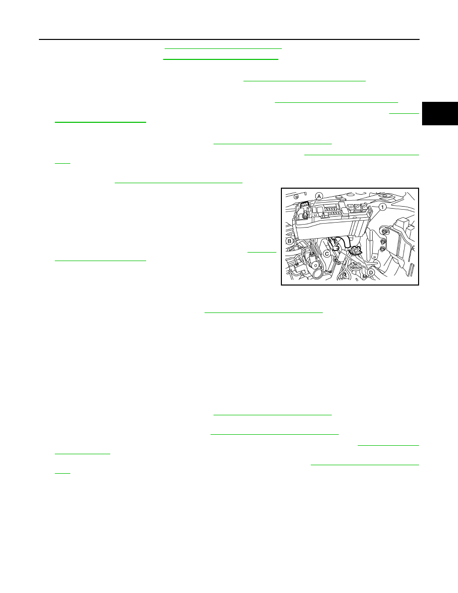
13. Remove the HV fuse box cover from the HV fuse box (1).
14. Remove the HV fuse box terminal cap and nuts (A) from the HV
fuse box (1).
15. Open the HV fuse box side cover (B) and remove the harness
retaining clip (C) and HV fuse box terminals from the HV fuse
box (1).
16. Disconnect the EPS ECU connectors (D). Refer to
17. Remove the EPS ECU harness retaining clips from the engine
room.
18. Remove the EPS ECU bonding wire bolt.
19. Remove the frame wire harness retaining clips from the engine room.
20. Remove the RH member pin stay. Refer to
EM-71, "Removal and Installation"
.
21. Remove the frame wire retainer nuts and bolts from the underside of vehicle.
22. Remove the frame wire harness assembly with grommet from floor pass through and underside of vehicle.
23. Remove the frame wire harness from the engine room clip and remove the frame wire harness from the
engine room.
Installation
Installation is in the reverse order of removal.
FRAME WIRE (ELECTRIC COMPRESSOR)
Removal
1. Remove the air cleaner and air duct. Refer to
EM-24, "Removal and Installation"
.
2. Remove the front terminal cover bolt from the inverter cover and disconnect the electric compressor
inverter connector from the inverter. Refer to
HBC-638, "Removal and Installation"
3. Disconnect the electric compressor connector from the electric compressor. Refer to
4. Remove the front engine mounting insulator and bracket bolts. Refer to
5. Remove the electric compressor frame wire harness clips and electric compressor frame wire harness
from the vehicle.
Installation
Installation is in the reverse order of removal.
ALCIA0081ZZ