Nissan Altima HL32 Hybrid. Manual - part 724


  Index      Nissan     Nissan Altima HL32 Hybrid (2009 year) - Service and Repair Manual


Search            


Content   ..  722  723  724  725   ..


Nissan Altima HL32 Hybrid. Manual - part 724


HV ECU

HBC-645

< REMOVAL AND INSTALLATION >

D

E

F

G

H

I

J

K

L

M

A

B

HBC

N

O

P

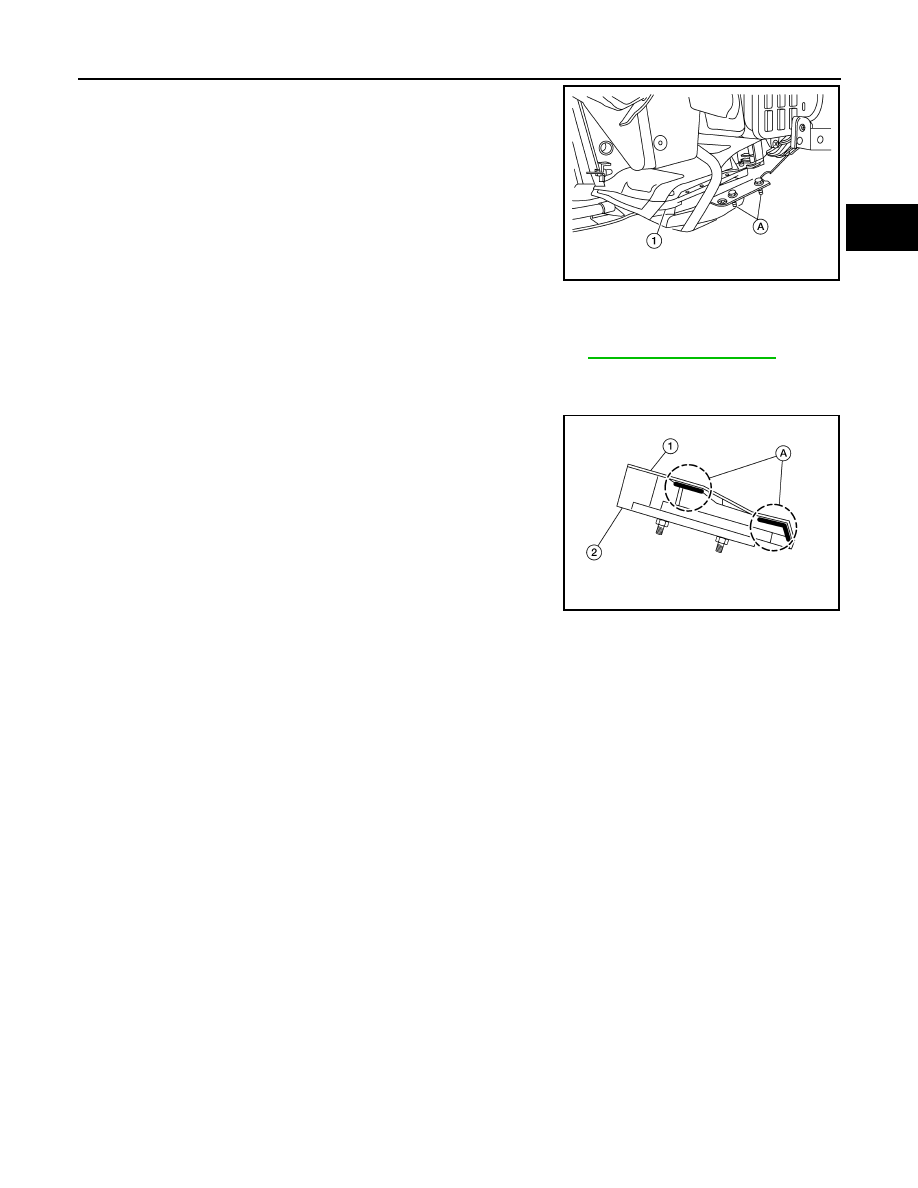
4. Remove the bolts (A) from the HV ECU (1).
5. Disconnect the drain hose from the heater and cooling unit

assembly.

6. Pull out the HV ECU to RH side.
7. Disconnect the HV ECU harness connector from the HV ECU,

and remove the HV ECU from the vehicle.

8. If necessary, remove the screws and HV ECU brackets from the

HV ECU.

INSTALLATION

Installation is in the reverse order of removal.

NOTE:

• When tightening the bolts, perform the following procedure and refer to 

HBC-644, "Exploded View"

.

- Temporarily tighten bolt (A) first.

- Tighten the other bolts in numerical order to the specified torque.

- Tighten bolt (A) to the specified torque. 

• If installing a new HV ECU, apply the waterproof sheet (1) to the

HV ECU (2) as shown. Center the waterproof sheet on the HV

ECU and press down on the adhesive area (A) to secure the

waterproof sheet to the HV ECU.

ALCIA0086ZZ

ALCIA0099ZZ

HBC-646

< REMOVAL AND INSTALLATION >

SUB RADIATOR

SUB RADIATOR

Exploded View

INFOID:0000000004212223

Removal and Installation

INFOID:0000000004212224

REMOVAL

CAUTION:

Do not damage or scratch the radiator and condenser assembly and sub radiator core when removing.
1. Drain the coolant from the inverter cooling system. Refer to 

HBC-636, "Replacement"

.

2. Remove the air duct. Refer to 

EM-24, "Removal and Installation"

.

3. Remove the front grille. Refer to 

EXT-16, "Removal and Installation"

.

4. Disconnect the clamp (A) and the upper outlet hose (1) from the

sub radiator (2).

1.

Rubber bushing

2.

Sub radiator

3.

Clamp

4.

Upper outlet hose

5.

Inverter coolant reservoir tank

6.

Lower inlet hose

A.

To inverter

B.

To transaxle

Front

AWCIA0040GB

AWCIA0041ZZ

SUB RADIATOR

HBC-647

< REMOVAL AND INSTALLATION >

D

E

F

G

H

I

J

K

L

M

A

B

HBC

N

O

P

5. Disconnect the clamp (A) and the lower inlet hose (1) from the

sub radiator (2).

6. Remove the bolts (A), then remove the sub radiator (1) from the

vehicle.

INSTALLATION

Installation is in the reverse order of removal.

ALCIA0090ZZ

ALCIA0091ZZ

HBC-648

< REMOVAL AND INSTALLATION >

FRAME WIRE

FRAME WIRE

Exploded View

INFOID:0000000004212225

Removal and Installation

INFOID:0000000004212226

FRAME WIRE (MAIN)

Removal

1. Disconnect the positive 12 volt terminal from the 12 volt battery. Refer to 

PG-69, "Removal and Installa-

tion"

.

1.

Frame wire (electric compressor)

2.

Frame wire (main)

A.

Electric compressor connector

B.

Electric compressor inverter connec-
tor

C.

Frame wire inverter connector

D.

HV fuse box terminals

E.

EPS ECU connectors

F.

EPS ECU bonding wire

G.

Grommet

H.

Frame wire terminals to HV battery

I.

12 volt terminal to HV battery

J.

DC/DC converter connectors

K.

12 volt terminal to 12 volt battery

⇐: Front

ALCIA0095GB


Content   ..  722  723  724  725   ..