Nissan Altima HL32 Hybrid. Manual - part 723
WATER PUMP WITH MOTOR & BRACKET ASSEMBLY
HBC-641
< REMOVAL AND INSTALLATION >
D
E
F
G
H
I
J
K
L
M
A
B
HBC
N
O
P
WATER PUMP WITH MOTOR & BRACKET ASSEMBLY
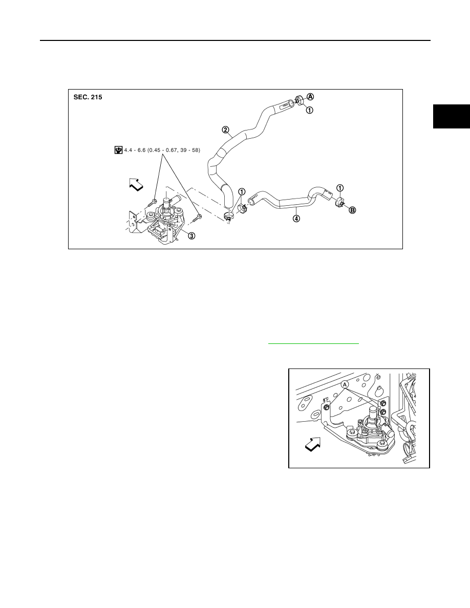
Exploded View
INFOID:0000000004212216
Removal and Installation
INFOID:0000000004212217
REMOVAL
1. Drain the coolant from the inverter cooling system. Refer to
.
2. Disconnect the water inlet hose and water outlet hose from the water pump with motor and bracket
assembly.
3. Remove the bolts (A) from the water pump with motor and
bracket assembly and remove from the vehicle.
•
⇐: Front
Installation
Installation is in the reverse order of removal.
NOTE:
Do not use the power tool.
1.
Clamp
2.
Water inlet hose
3.
Water pump with motor and bracket
assembly
4.
Water outlet hose
A. To inverter coolant reservoir tank
B.
To transaxle
⇐: Front
JMCIA0175GB
ALCIA0085ZZ