Nissan Altima HL32 Hybrid. Manual - part 721


  Index      Nissan     Nissan Altima HL32 Hybrid (2009 year) - Service and Repair Manual


Search            


Content   ..  719  720  721  722   ..


Nissan Altima HL32 Hybrid. Manual - part 721


PRECAUTIONS

HBC-633

< PRECAUTION >

D

E

F

G

H

I

J

K

L

M

A

B

HBC

N

O

P

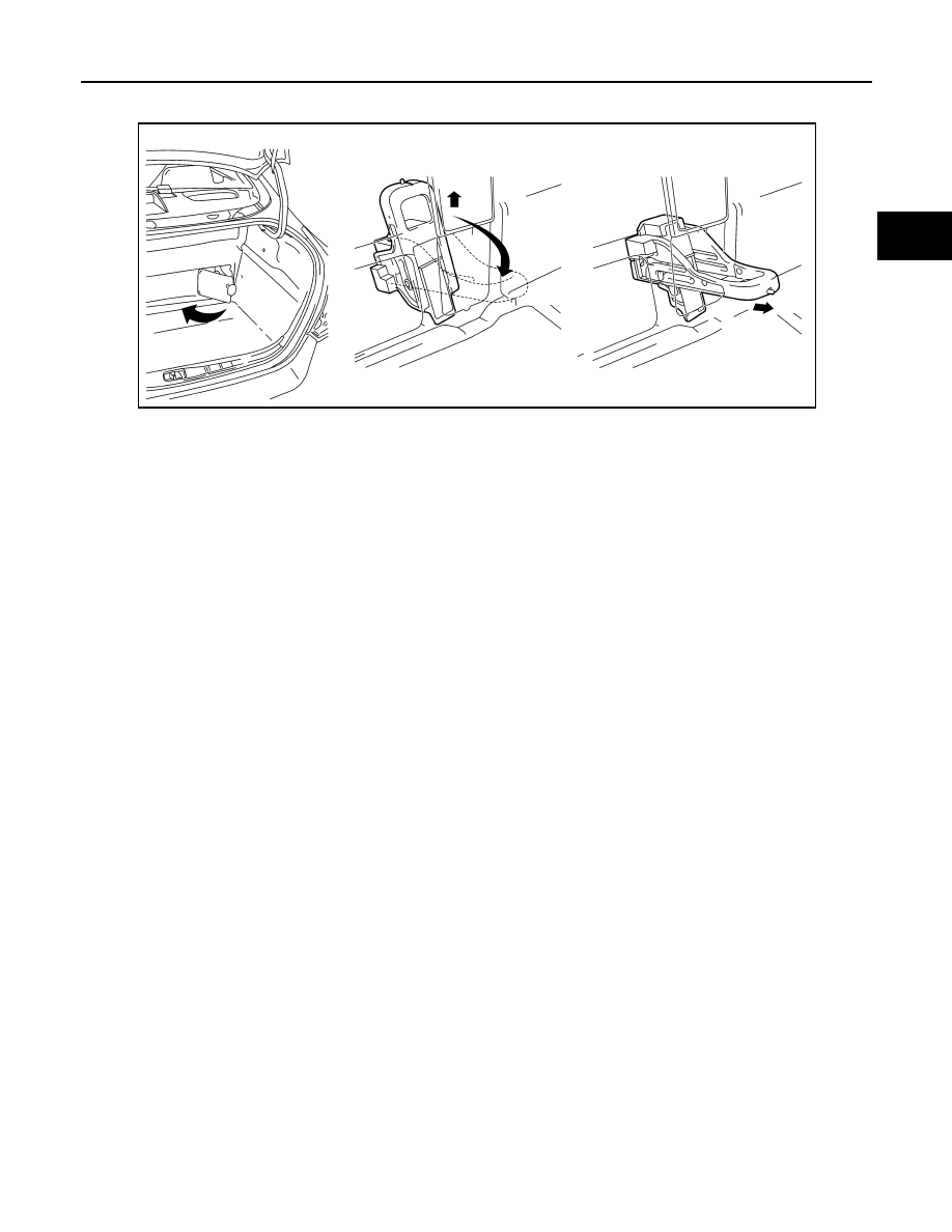
plug grip. After removing the service plug grip, put it in your pocket to prevent other technicians from acci-

dentally reconnecting it while you are working on the high-voltage system.

NOTE:

Turning ignition switch ON (READY) with the service plug grip removed could cause a malfunction.

Do not turn ignition switch ON (READY) unless instructed by the service manual.

ON (READY): The condition which the ready indicator lamp illuminates and vehicle is ready to be

driven.

• After disconnecting the service plug grip, wait for at least 10 minutes before touching any of the high-voltage

connectors or terminals.

NOTE:

Waiting for at least 10 minutes is required to discharge the high-voltage capacitor inside the inverter with

converter assembly.

• Turn ignition switch OFF, wear insulated gloves, and disconnect the negative terminal of the auxiliary battery

before touching any of the orange-colored wires of the high-voltage system.

• Turn ignition switch OFF before performing any resistance checks.

• Turn ignition switch OFF before disconnecting or reconnecting any connectors.

Precautions for the Hybrid Control System Activation

INFOID:0000000004212206

• When the auxiliary battery has been disconnected and reconnected, attempting to turn ignition switch ON

(READY) may not start the system (the system may not enter the READY-on state) on the first attempt. If so,

turn ignition switch OFF and reattempt to turn ignition switch ON (READY).

Precaution for Supplemental Restraint System (SRS) "AIR BAG" and "SEAT BELT 
PRE-TENSIONER"

INFOID:0000000004212207

The Supplemental Restraint System such as “AIR BAG” and “SEAT BELT PRE-TENSIONER”, used along

with a front seat belt, helps to reduce the risk or severity of injury to the driver and front passenger for certain

types of collision. This system includes seat belt switch inputs and dual stage front air bag modules. The SRS

system uses the seat belt switches to determine the front air bag deployment, and may only deploy one front

air bag, depending on the severity of a collision and whether the front occupants are belted or unbelted.

Information necessary to service the system safely is included in the SR and SB section of this Service Man-

ual.

WARNING:

• To avoid rendering the SRS inoperative, which could increase the risk of personal injury or death in

the event of a collision which would result in air bag inflation, all maintenance must be performed by

an authorized NISSAN/INFINITI dealer.

• Improper maintenance, including incorrect removal and installation of the SRS, can lead to personal

injury caused by unintentional activation of the system. For removal of Spiral Cable and Air Bag

Module, see the SR section.

• Do not use electrical test equipment on any circuit related to the SRS unless instructed to in this

Service Manual. SRS wiring harnesses can be identified by yellow and/or orange harnesses or har-

ness connectors.

ALCIA0007ZZ

HBC-634

< PRECAUTION >

PRECAUTIONS

Precaution for replacing hybrid vehicle control ECU

INFOID:0000000004212208

When replacing the hybrid vehicle control ECU, never remove the waterproof sheet.

NOTE:

The hybrid vehicle control ECU is covered with a waterproof sheet. If the waterproof sheet is peeled off, the

labels on the hybrid vehicle control ECU will be removed together with the waterproof sheet. Consequently

important data printed on the label for warranty procedure will be lost.

Necessary for Steering Wheel Rotation After Battery Disconnect

INFOID:0000000004466822

NOTE:

• Before removing and installing any control units, first turn the push-button ignition switch to the LOCK posi-

tion, then disconnect both 12-volt battery cables.

• After finishing work, confirm that all control unit connectors are connected properly, then re-connect both 12-

volt battery cables.

• Always use CONSULT-III to perform self-diagnosis as a part of each function inspection after finishing work.

If a DTC is detected, perform trouble diagnosis according to self-diagnosis results.

This vehicle is equipped with a push-button ignition switch and a steering lock unit.

If the 12-volt battery is disconnected or discharged, the steering wheel will lock and cannot be turned.

If turning the steering wheel is required with the 12-volt battery disconnected or discharged, follow the proce-

dure below before starting the repair operation.

OPERATION PROCEDURE

1. Connect both 12-volt battery cables.

NOTE:

Supply power using jumper cables if 12-volt battery is discharged.

2. Carry the Intelligent Key or insert it to the key slot and turn the push-button ignition switch to ACC position.

(At this time, the steering lock will be released.)

3. Disconnect both 12-volt battery cables. The steering lock will remain released with both 12-volt battery

cables disconnected and the steering wheel can be turned.

4. Perform the necessary repair operation.
5. When the repair work is completed, re-connect both 12-volt battery cables. With the brake pedal released,

turn the push-button ignition switch from ACC position to ON position, then to LOCK position. (The steer-

ing wheel will lock when the push-button ignition switch is turned to LOCK position.)

6. Perform self-diagnosis check of all control units using CONSULT-III.

Precaution for Procedure without Cowl Top Cover

INFOID:0000000004212209

When performing the procedure after removing cowl top cover, cover

the lower end of windshield with urethane, etc.

PIIB3706J

PREPARATION

HBC-635

< PREPARATION >

D

E

F

G

H

I

J

K

L

M

A

B

HBC

N

O

P

PREPARATION

PREPARATION

Commercial Service Tools

INFOID:0000000004212211

Tool name
(Kent-Moore No.)

Description

Insulation gloves

Guaranteed insulation performance for 1000V/300A

JMCIA0149ZZ

HBC-636

< ON-VEHICLE MAINTENANCE >

COOLANT(FOR INVERTER)

ON-VEHICLE MAINTENANCE

COOLANT(FOR INVERTER)

Inspection

INFOID:0000000004212212

WARNING:

• Never remove the inverter cooling reservoir tank cap when the engine or inverter are hot. Serious

burns could occur from high pressure coolant escaping from the inverter coolant reservoir tank.

• Wrap a thick cloth around the cap. Slowly push down and turn cap a quarter turn to allow built-up

pressure to escape. Carefully remove the cap by pushing down and turning it all the way.

CHECKING COOLANT LEVEL (INVERTER COOLING SYSTEM)

1. Check if the coolant level in the inverter cooling reservoir tank

(1) is within MIN (B) to MAX (A) when coolant is cool.

⇐: Front

2. Adjust inverter cooling system coolant level as necessary. Refer

to 

HBC-636, "Replacement"

.

CHECKING COOLANT CONDITION (INVERTER COOLING SYSTEM)

• Check for excessive deposits of dirt or rust in the inverter cooling system coolant.

• If the coolant contains excessive dirt or rust, replace the inverter cooling system coolant. Refer to 

HBC-636,

"Replacement"

.

Replacement

INFOID:0000000004212213

DRAINING COOLANT

WARNING:

• Never remove the inverter cooling reservoir tank cap when the engine or inverter are hot. Serious

burns could occur from high pressure coolant escaping from the inverter coolant reservoir tank.

• Wrap a thick cloth around the cap. Slowly push down and turn cap a quarter turn to allow built-up

pressure to escape. Carefully remove the cap by pushing down and turning it all the way.

1. Remove the inverter cooling reservoir tank cap (1).

⇐: Front

2. Remove the engine under cover. Refer to 

EXT-12, "Removal and Installation"

.

ALCIA0076ZZ

ALCIA0073ZZ


Content   ..  719  720  721  722   ..