Nissan Altima HL32 Hybrid. Manual - part 719


  Index      Nissan     Nissan Altima HL32 Hybrid (2009 year) - Service and Repair Manual


Search            


Content   ..  717  718  719  720   ..


Nissan Altima HL32 Hybrid. Manual - part 719


HV ECU

HBC-625

< ECU DIAGNOSIS >

D

E

F

G

H

I

J

K

L

M

A

B

HBC

N

O

P

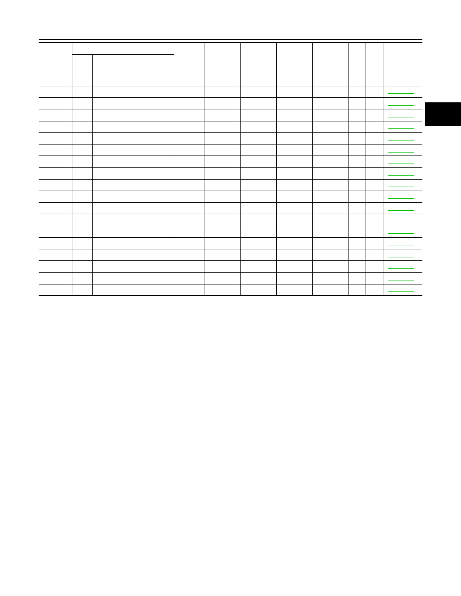
*1: Warning light illuminates until the DTC is cleared from the hybrid vehicle control ECM memory.
*2: This DTC indicates that a malfunction exists in the engine control system. So, erase the DTC in the hybrid vehicle control ECU mem-
ory, then perform the corresponding trouble diagnosis referring the work flow in EC section.

U0110

159

LOST COMM (MG ECM)

x

x

1

HBC-574

U0110

160

LOST COMM (MG ECM)

x

x

1

HBC-574

U0110

656

LOST COMM (MG ECM)

x

x

1

HBC-574

U0110

657

LOST COMM (MG ECM)

x

x

1

HBC-574

U0115

901

LOST COMM (COUNT)

1

HBC-580

U0129

220

LOST COMM (BRAKE)

1

HBC-582

U0129

222

LOST COMM (BRAKE)

1

HBC-582

U0129

528

LOST COMM (BRAKE)

1

HBC-582

U0129

529

LOST COMM (BRAKE)

x

1

HBC-583

U0131

433

LOST COMM (EPS)

1

HBC-585

U0131

434

LOST COMM (EPS)

1

HBC-585

U0424

537

HVAC COTROL UNIT

x

1

HBC-586

U1001

146

CAN COMM CIRCUIT

x

1

HBC-587

U1001

435

CAN COMM CIRCUIT

x

1

HBC-587

U1001

594

CAN COMM CIRCUIT

1

HBC-587

U1001

827

CAN COMM CIRCUIT

1

HBC-587

U1001

919

CAN COMM CIRCUIT

x

1

HBC-587

U1001

920

CAN COMM CIRCUIT

x

1

HBC-587

DTC

CONSULT-III display

GST 

display

FRZF

Informa-

tion data 

Hybrid 

system 

warning 

light

High volt-

age bat-

tery 

warning 

light

Charge 

warning 

light

MIL Trip

Reference 

page

INF 

code

Item

HBC-626

< ECU DIAGNOSIS >

MG ECU

MG ECU

Reference Value

INFOID:0000000004212202

TERMINAL LAYOUT

PHYSICAL VALUES

NOTE:

• Do not measure voltage or waveform directly at the sealed side of the inverter with converter assembly con-

nectors. Doing so may damage the connectors because these connectors are waterproof.

• Oscilloscope waveform samples are provided here for informational purposes. Noise and fluttering wave-

forms have been omitted.

JMCIA0168ZZ

Terminal No.

Wire color

Description

Condition

Value

(Approx.)

+

Signal name

Input/

Output

41

42

O - L/G

Generator re-
solver signal

Input/

Output

[Ignition switch: 
READY]
• Generator resolver: 

Stopped or running

Refer to CH2 signal.
Pulse cycle A becomes shorter as the rotor speed 
increased.

43

44

L/Y -  O/L

Generator re-
solver signal

Input/

Output

[Ignition switch: 
READY]
• Generator resolver: 

Stopped or running

Refer to CH3 signal.
Pulse cycle A becomes shorter as the rotor speed 
increased.

JMCIA0028GB

JMCIA0028GB

MG ECU

HBC-627

< ECU DIAGNOSIS >

D

E

F

G

H

I

J

K

L

M

A

B

HBC

N

O

P

46

45

W/L - W

Generator re-
solver signal

Input/

Output

[Ignition switch: 
READY]
• Generator resolver: 

Stopped or running

Refer to CH1 signal.
Pulse cycle A becomes shorter as the rotor speed 
increased.

48

49

L/Y - O/L

Motor resolver 
signal

Input/

Output

[Ignition switch: 
READY]
• Motor resolver: 

Running

Refer to CH3 signal.
Pulse cycle A becomes shorter as the rotor speed 
increased.

51

47

O - L/G

Motor resolver 
signal

Input/

Output

[Ignition switch: ON]
• Motor resolver: 

Running

Refer to CH2 signal.
Pulse cycle A becomes shorter as the rotor speed 
increased.

Terminal No.

Wire color

Description

Condition

Value

(Approx.)

+

Signal name

Input/

Output

JMCIA0028GB

JMCIA0024GB

JMCIA0024GB

HBC-628

< ECU DIAGNOSIS >

MG ECU

53

52

W/L - W

Motor resolver 
signal

Input/

Output

[Ignition switch: 
READY]
• Motor resolver: 

Running

Refer to CH1 signal.
Pulse cycle A becomes shorter as the rotor speed 
increased.

31

3

L/W - B

MG shutdown 
signal

Output

[Ignition switch: 
READY]

0 - 1V

30

3

P - B

PHASE signal

Input

[Ignition switch: 
ready]
• Engine: Idle

The pulse cycle becomes shorter as the engine 
speed increased.

28

3

BR/R - B

Communication 
signal from MG 
ECU to hybrid 
vehicle control 
ECU

Output [Ignition switch: ON]

Refer to CH2 signal.
The waveform will vary depending on the content 
of the digital communication (digital signal).

Terminal No.

Wire color

Description

Condition

Value

(Approx.)

+

Signal name

Input/

Output

JMCIA0024GB

JMCIA0024GB

JMCIA0026GB


Content   ..  717  718  719  720   ..