Nissan Altima HL32 Hybrid. Manual - part 698


  Index      Nissan     Nissan Altima HL32 Hybrid (2009 year) - Service and Repair Manual


Search            


Content   ..  696  697  698  699   ..


Nissan Altima HL32 Hybrid. Manual - part 698


P3004-803

HBC-541

< COMPONENT DIAGNOSIS >

D

E

F

G

H

I

J

K

L

M

A

B

HBC

N

O

P

P3004-803

Description

INFOID:0000000004212130

The SMRs (System Main Relay) are the relays that connect or disconnect the high voltage power system in

accordance with commands from the hybrid vehicle control ECU.

The SMR system is composed of three SMRs and one system main resistor. SMRB and SMRG are located on

the HV relay assembly in the battery carrier under the HV battery. SMRP and the system main resistor are

located in the hybrid vehicle converter (DC/DC converter) assembly in the battery carrier.

To connect to the high voltage power system, the vehicle will first turn on SMRP and SMRB to charge the vehi-

cle through the system main resistor. Then, SMRP will be turned off after the SMRG is turned on. To shut off

the high voltage power system, SMRB and SMRG are turned off.

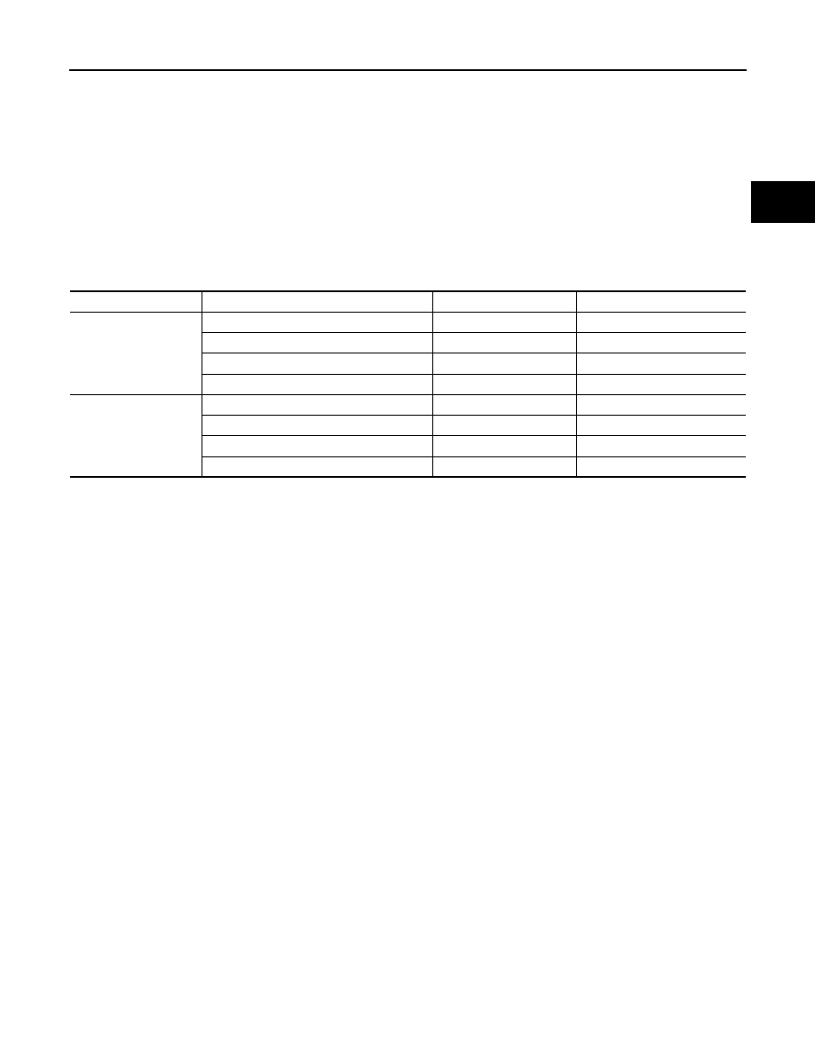
When there is an open in the AMD line or IGCT line, the following DTCs are output:

P0AE6-225 is output first because the time required for diagnosis is the shortest.

Trouble area

Malfunction

DTC

Occurrence condition

Open in AMD line

DC/DC converter malfunction

P0A08-264

May not occur

Open in VLO, short to GND

P0A09-591

May not occur

IDH frequency error

P2519-766

Occurs

Open in SMRP, short to GND

P0AE6-225

Occurs

Open in IGCT line

Open in NODD, short to GND

P0A09-265

Occurs

Open in VLO, short to GND

P0A09-591

Occurs

IDH frequency error

P2519-766

Occurs

Open in SMRP, short to GND

P0AE6-225

Occurs

HBC-542

< COMPONENT DIAGNOSIS >

P3004-803

JMCIA0198GB

P3004-803

HBC-543

< COMPONENT DIAGNOSIS >

D

E

F

G

H

I

J

K

L

M

A

B

HBC

N

O

P

DTC Logic

INFOID:0000000004212131

DTC DETECTION LOGIC

Diagnosis Procedure

INFOID:0000000004212132

1.

PRECONDITIONING

• Before inspecting the high-voltage system or disconnecting the low voltage connector of the inverter with

converter assembly, take safety precautions such as wearing insulated gloves and removing the service

plug grip to prevent electrical shocks. After removing the service plug grip, put it in your pocket to prevent

other technicians from accidentally reconnecting it while you are working on the high-voltage system.

• After disconnecting the service plug grip, wait for at least 10 minutes before touching any of the high-voltage

connectors or terminals.

• Waiting for at least 10 minutes is required to discharge the high-voltage capacitor inside the inverter with

converter assembly.

>> GO TO 2.

JMCIA0125GB

DTC No.

INF code

Trouble diagnosis name

DTC detecting condition

Possible cause

P3004

803

Power cable malfunction

While the ignition switch ON 
(READY), the voltage in the inverter 
with converter assembly (VL, VH) 
decreases.

• Wire harness or connector
• HV relay assembly

HBC-544

< COMPONENT DIAGNOSIS >

P3004-803

2.

CHECK DTC OUTPUT (HYBRID SYSTEM)

1. Turn ignition switch ON.

2. Check DTC.

Is DTC detected?

YES

>> Go to Diagnosis Procedure relevant to output DTC.

NO

>> GO TO 3.

3.

CLEAR DTC

1. Turn ignition switch ON.

2. Read and record the DTCs and freeze frame data.

3. Clear DTC.

>> GO TO 4.

4.

RECONFIRM DTC OUTPUT

1. Turn ignition switch ON (READY), move the shift lever to the D position, and depress both the accelerator

pedal and brake pedal.

NOTE:

• Depressing both the accelerator pedal and brake pedal causes the HV battery current to flow and can

be used to check that there is no problem with the high-voltage wiring.

• Depressing both the accelerator pedal and brake pedal causes “ACCEL & BRK” in the inappropriate

operation history data to be counted.

2. Check DTC.

A or B

A

>> GO  TO  5.

B

>> Go to Diagnosis Procedure relevant to output DTC. (P3004-131)

5.

CHECK CONNECTOR CONNECTION CONDITION (HYBRID VEHICLE CONTROL ECU CONNECTOR)

See 

HBC-109, "Diagnosis Procedure"

.

OK or NG

OK

>> GO TO 6.

NG

>> Connect securely.

6.

CHECK CONNECTOR CONNECTION CONDITION (BATTERY PACK WIRE CONNECTOR)

See 

HBC-140, "Diagnosis Procedure"

.

OK or NG

OK

>> GO TO 7.

NG

>> Connect securely.

7.

CHECK HARNESS AND CONNECTOR (HYBRID VEHICLE CONTROL ECU - BATTERY PACK WIRE

CONNECTOR)

CAUTION:

Be sure to wear insulated gloves.

DTC No.

Relevant Part

P0A95, P0AFA

Open in electric vehicle fuse

P0ADF-229, P0AE0-228

SMRG control line

P0ADC-226, P0ADB-227

SMRB control line

P0A1A-156, 658, 659, 151, 155, P0A1B-511, 164, 163, 512, 193, 786, 788, 661, P0A78-266, 
267, 523, 586, P0A94-442

VH sensor circuit

Result

Proceed to

P3004-803 is output, or no DTCs are output.

A

Ignition switch is not turned ON (READY) and P3004-131 is output.

B


Content   ..  696  697  698  699   ..