Index Nissan Nissan Altima HL32 Hybrid (2009 year) - Service and Repair Manual
Search
Content .. 676 677 678 679 ..
Nissan Altima HL32 Hybrid. Manual - part 678
P0AE6-225
HBC-461
< COMPONENT DIAGNOSIS >
D
E
F
G
H
I
J
K
L
M
A
B
HBC
N
O
P
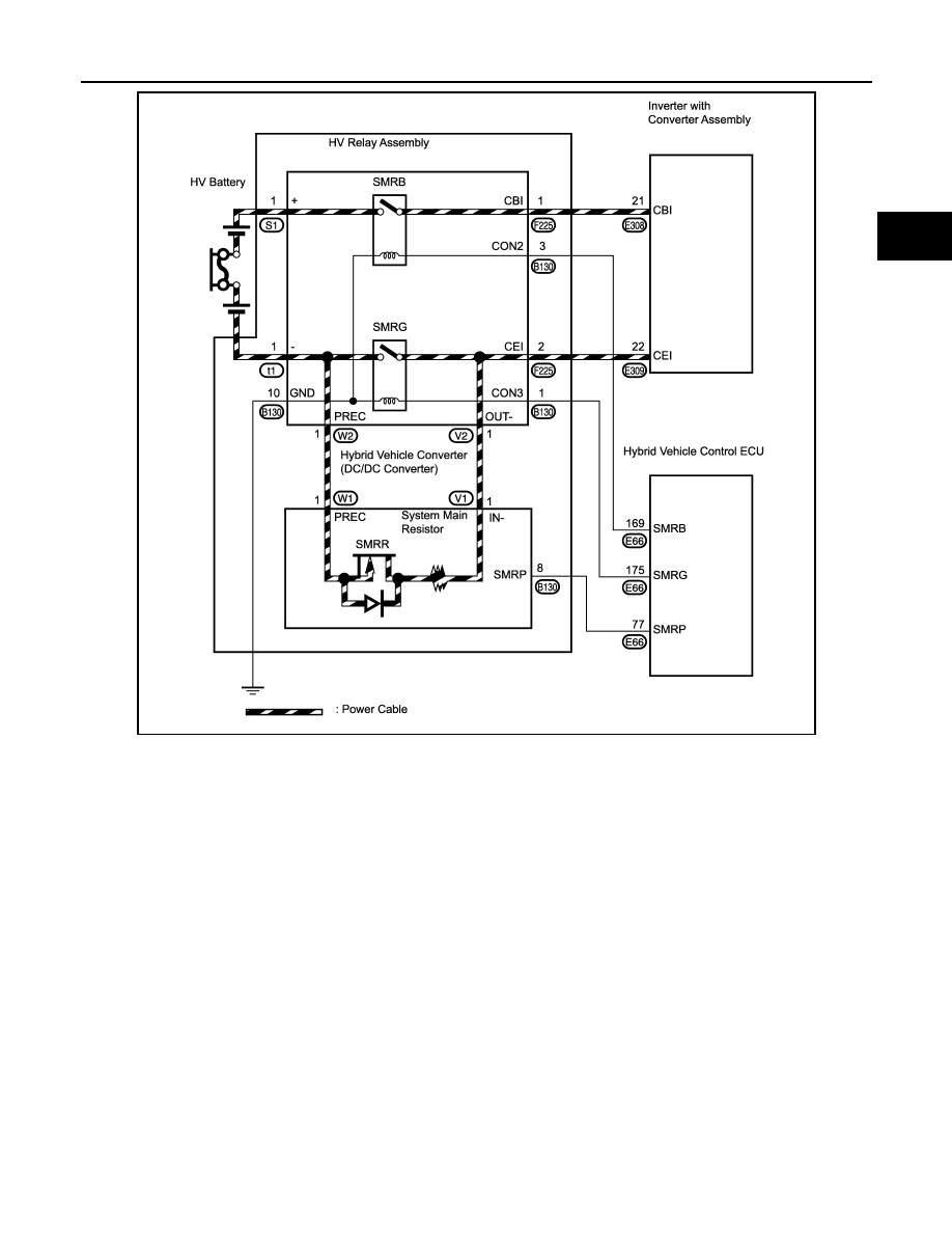
JMCIA0124GB