Nissan Altima HL32 Hybrid. Manual - part 679
P0AE6-225
HBC-465
< COMPONENT DIAGNOSIS >
D
E
F
G
H
I
J
K
L
M
A
B
HBC
N
O
P
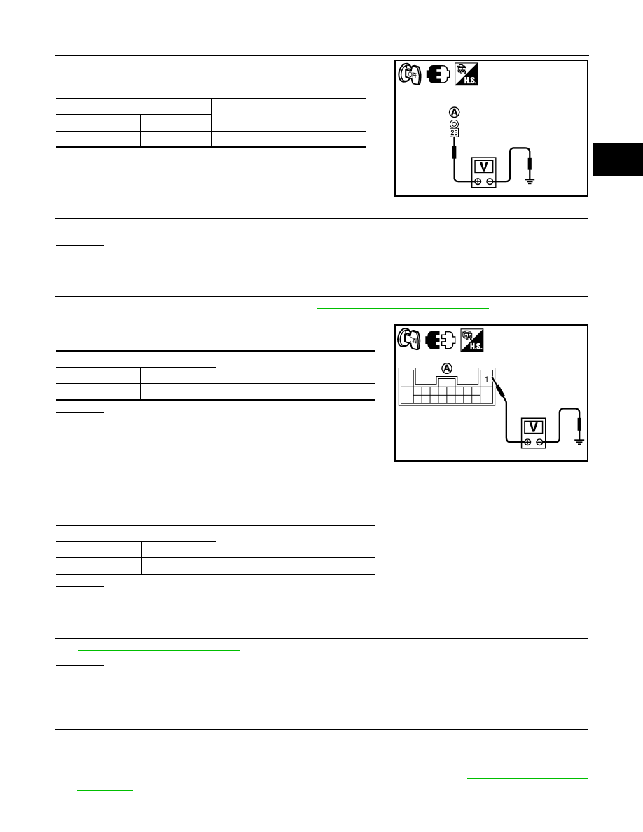
2. Measure the voltage according to the value(s) in the table below
when the ignition switch OFF.
OK or NG
OK
>> GO TO 8.
NG
>> Repair or replace frame wire.
8.
CHECK CONNECTOR CONNECTION CONDITION (BATTERY PACK WIRE CONNECTOR)
HBC-140, "Diagnosis Procedure"
OK or NG
OK
>> GO TO 9.
NG
>> Connect securely.
9.
CHECK HARNESS AND CONNECTOR
1. Disconnect the battery pack wire connector (See
HBB-97, "Removal and Installation"
).
2. Turn ignition switch ON.
3. Measure the voltage according to the value(s) in the table below.
OK or NG
OK
>> GO TO 10.
NG
>> Repair or replace harness or connector.
10.
CHECK HYBRID VEHICLE CONTROL ECU
1. Turn ignition switch OFF.
2. Measure the resistance according to the value(s) in the table below.
OK or NG
OK
>> GO TO 11.
NG
>> GO TO 13.
11.
CHECK CONNECTOR CONNECTION CONDITION (HYBRID VEHICLE CONVERTER CONNECTOR)
HBC-140, "Diagnosis Procedure"
OK or NG
OK
>> GO TO 12.
NG
>> Connect securely.
12.
CHECK HARNESS AND CONNECTOR (HYBRID VEHICLE CONVERTER - BATTERY PACK WIRE
CONNECTOR)
CAUTION:
Be sure to wear insulated gloves.
1. Check that the service plug grip is not installed.
2. Disconnect the n4 hybrid vehicle converter (DC/DC converter) connector (See
).
Frame Wire (A)
Ground
Voltage
Harness connector
Terminal
E312
25
Ground
9 to 14V
JMCIA0230ZZ
Battery pack wire connector (A)
Ground
Voltage
Harness connector
Terminal
B130
1 (IGCT)
Ground
9 to 14V
JMCIA0231ZZ
Battery pack wire connector
Ground
Resistance
Harness connector
Terminal
B130
8 (SMRP)
Ground
370 to 430 k
Ω