Nissan Altima HL32 Hybrid. Manual - part 676


  Index      Nissan     Nissan Altima HL32 Hybrid (2009 year) - Service and Repair Manual


Search            


Content   ..  674  675  676  677   ..


Nissan Altima HL32 Hybrid. Manual - part 676


P0AE2-161

HBC-453

< COMPONENT DIAGNOSIS >

D

E

F

G

H

I

J

K

L

M

A

B

HBC

N

O

P

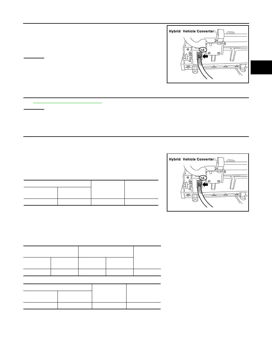
2. Check the connection of the low voltage connector of the hybrid

vehicle converter (DC/DC converter).

OK or NG

OK

>> GO TO 9.

NG

>> Connect securely.

9.

CHECK CONNECTOR CONNECTION CONDITION (HYBRID VEHICLE CONVERTER ASSEMBLY CON-

NECTOR)

See 

HBC-109, "Diagnosis Procedure"

.

OK or NG

OK

>> GO TO 10.

NG

>> Repair or replace harness or connector.

10.

CHECK HARNESS AND CONNECTOR (HYBRID VEHICLE CONVERTER - BATTERY PACK WIRE

CONNECTOR)

CAUTION:

Be sure to wear insulated gloves.

1. Check that the service plug grip is not installed.

2. Disconnect the n4 hybrid vehicle converter (DC/DC converter)

connector.

3. Turn ignition switch ON.

4. Measure the voltage according to the value(s) in the table below.

NOTE:

Turn ignition switch ON with the hybrid vehicle converter

(DC/DC converter) connector disconnected causes other DTCs to be stored. Clear the DTCs after

performing this inspection.

5. Turn ignition switch OFF.

6. Measure the resistance according to the value(s) in the table below.

Check for open

Check for short

The connector is connected securely and there are no 
contact problems.

JMCIA0160GB

Battery Pack Wire

Ground

Voltage

Harness

connector

Terminal

B130

8 (SMRP)

Ground

Below 1 V

JMCIA0160GB

Battery Pack Wire

Hybrid Vehicle Converter (DC/

DC Converter)

Resistance

Harness

connector

Terminal

Harness

connector

Terminal

B130

8 (SMRP)

n4

4 (SMRP)

Below 1 

Battery Pack Wire Connector

Ground

Resistance

Harness

connector

Terminal

B130

8 (SMRP)

Ground

10 k

Ω or higher

HBC-454

< COMPONENT DIAGNOSIS >

P0AE2-161

OK or NG

OK

>> GO TO 11.

NG

>> Repair or replace harness or connector.

11.

INSPECT HV RELAY ASSEMBLY (SMRG) 

See 

HBC-444, "Diagnosis Procedure"

.

OK or NG

OK 

>> Repair or replace harness or connector.

NG

>> Inspect HV relay assembly (SMRG) (See 

HBB-105, "Removal and Installation"

).

12.

INSPECT HV RELAY ASSEMBLY (SMRG)

See 

HBC-444, "Diagnosis Procedure"

.

OK or NG

OK

>> Replace hybrid vehicle converter.

NG

>> Replace HV relay assembly.

13.

CHECK HARNESS AND CONNECTOR (HYBRID VEHICLE CONTROL ECU - BATTERY PACK WIRE

CONNECTOR)
NOTE:

Be sure to wear insulated gloves.

1. Check that the service plug grip is not installed.

2. Disconnect the E66 hybrid vehicle control ECU connector.

3. Turn ignition switch ON.

4. Measure the voltage according to the value(s) in the table below.

NOTE:

Turn ignition switch ON with the hybrid vehicle control ECU connector disconnected causes other

DTCs to be stored. Clear the DTCs after performing this inspection.

5. Turn ignition switch OFF.

6. Measure the resistance according to the value(s) in the table below.

Check for open

Check for short

Hybrid Vehicle Converter (DC/DC Con-

verter)

Ground

Resistance

Harness

connector

Terminal

n4

4 (SMRP)

Ground

10 k

Ω or higher

Hybrid Vehicle Control ECU

Ground

Voltage

Harness connector

Terminal

E66

77 (SMRP)

Ground

Below 1 V

Hybrid Vehicle Control ECU

Battery Pack Wire

Resistance

Harness

connector

Terminal

Harness

connector

Terminal

E66

77 (SMRP)

B130

8 (SMRP)

Below 1 

Hybrid Vehicle Control ECU

Ground

Resistance

Harness connector

Terminal

E66

77 (SMRP)

Ground

10 k

Ω or higher

Battery Pack Wire

Ground

Resistance

Harness connector

Terminal

B130

8 (SMRP)

Ground

10 k

Ω or higher

P0AE2-161

HBC-455

< COMPONENT DIAGNOSIS >

D

E

F

G

H

I

J

K

L

M

A

B

HBC

N

O

P

OK or NG

OK

>> Replace hybrid vehicle control ECU.

NG

>> Repair or replace harness or connector.

HBC-456

< COMPONENT DIAGNOSIS >

P0AE2-773

P0AE2-773

Description

INFOID:0000000004212068

The SMRs (System Main Relay) are the relays that connect or disconnect the high voltage power system in

accordance with commands from the hybrid vehicle control ECU.

The SMR system is composed of three SMRs and one system main resistor. SMRB and SMRG are located on

the HV relay assembly in the battery carrier under the HV battery. SMRP and the system main resistor are

located in the hybrid vehicle converter (DC/DC converter) assembly in the battery carrier.

To connect to the high voltage power system, the vehicle will first turn on SMRP and SMRB to charge the vehi-

cle through the system main resistor. Then, SMRP will be turned off after the SMRG is turned on. To shut off

the high voltage power system, SMRB and SMRG are turned off.

When there is an open in the AMD line or IGCT line, the following DTCs are output:

P0AE6-225 is output first because the time required for diagnosis is the shortest.

Trouble area

Malfunction

DTC

Occurrence condition

Open in AMD line

DC/DC converter malfunction

P0A08-264

May not occur

Open in VLO, short to GND

P0A09-591

May not occur

IDH frequency error

P2519-766

Occurs

Open in SMRP, short to GND

P0AE6-225

Occurs

Open in IGCT line

Open in NODD, short to GND

P0A09-265

Occurs

Open in VLO, short to GND

P0A09-591

Occurs

IDH frequency error

P2519-766

Occurs

Open in SMRP, short to GND

P0AE6-225

Occurs


Content   ..  674  675  676  677   ..