Index Nissan Nissan Altima HL32 Hybrid (2009 year) - Service and Repair Manual
Search
Content .. 663 664 665 666 ..
Nissan Altima HL32 Hybrid. Manual - part 665
P0AA1-231
HBC-409
< COMPONENT DIAGNOSIS >
D
E
F
G
H
I
J
K
L
M
A
B
HBC
N
O
P
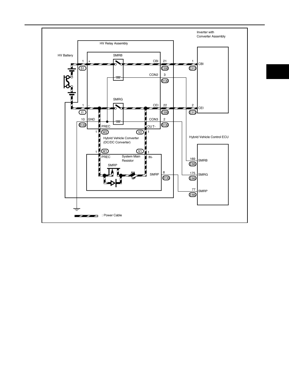
JMCIA0198GB