Nissan Altima HL32 Hybrid. Manual - part 602


  Index      Nissan     Nissan Altima HL32 Hybrid (2009 year) - Service and Repair Manual


Search            


Content   ..  600  601  602  603   ..


Nissan Altima HL32 Hybrid. Manual - part 602


P0A10-263

HBC-157

< COMPONENT DIAGNOSIS >

D

E

F

G

H

I

J

K

L

M

A

B

HBC

N

O

P

2. Disconnect the battery pack wire connector B130 (See 

HBB-97, "Removal and Installation"

).

3. Turn ignition switch ON.

4. Measure the voltage according to the value(s) in the table below.

NOTE:

Turning ignition switch ON with the battery pack wire connector

disconnected causes other DTCs to be stored. Clear the DTCs

after performing this inspection.

OK or NG

OK

>> GO TO 4.

NG

>> GO TO 5.

4.

CHECK HARNESS AND CONNECTOR (BATTERY PACK WIRE CONNECTOR - HYBRID VEHICLE CON-

VERTER)

CAUTION:

Be sure to wear insulated gloves.

1. Turn ignition switch OFF.

2. Check that the service plug grip is not installed.

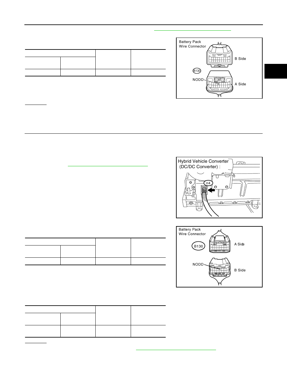
3. Disconnect the hybrid vehicle converter (DC/DC converter) con-

nector n4 (See 

HBB-103, "Removal and Installation"

).

4. Turn ignition switch ON.

5. Measure the voltage according to the value(s) in the table below.

NOTE:

Turning ignition switch ON with the battery pack wire connector

disconnected causes other DTCs to be stored. Clear the DTCs

after performing this inspection.

6. Turn ignition switch OFF.

7. Measure the resistance according to the value(s) in the table below.

OK or NG

OK

>> Replace hybrid vehicle converter (See 

HBC-644, "Removal and Installation"

).

NG

>> Repair or replace harness or connector.

Battery pack wire

Ground

Voltage

Harness

connector

Terminal

B130

6 (NODD)

Ground

Below 1 V

JMCIA0177GB

JMCIA0187GB

Battery pack wire

Ground

Voltage

Component

connector

Terminal

B130

6 (NODD)

Ground

Below 1 V

Battery pack wire connector

Ground

Resistance

Component

connector

Terminal

B130

6 (NODD)

Each of the other 

terminals

10 k

Ω or higher

JMCIA0189GB

HBC-158

< COMPONENT DIAGNOSIS >

P0A10-263

5.

CHECK HARNESS AND CONNECTOR (HYBRID VEHICLE CONTROL ECU - BATTERY PACK WIRE)

1. Disconnect the hybrid vehicle control ECU harness connector E66.

2. Turn ignition switch ON.

3. Measure the voltage according to the value(s) in the table below.

NOTE:

Turning ignition switch ON with the battery pack wire connector

disconnected causes other DTCs to be stored. Clear the DTCs

after performing this inspection.

OK or NG

OK

>> Replace hybrid vehicle control ECU (See 

HBC-644, "Removal and Installation"

).

NG

>> Repair or replace harness or connector.

Battery pack wire

Ground

Voltage

Harness

connector

Terminal

B130

6 (NODD)

Ground

Below 1 V

JMCIA0177GB

P0A10-592

HBC-159

< COMPONENT DIAGNOSIS >

D

E

F

G

H

I

J

K

L

M

A

B

HBC

N

O

P

P0A10-592

Description

INFOID:0000000004211807

The hybrid vehicle converter (DC/DC converter) controls output voltage based on voltage switching signals

sent from the hybrid vehicle control ECU.

DTC Logic

INFOID:0000000004211808

DTC DETECTION LOGIC

Diagnosis Procedure

INFOID:0000000004211809

1.

PRECONDITIONING

• Before inspecting the high-voltage system or disconnecting the low voltage connector of the inverter with

converter assembly, take safety precautions such as wearing insulated gloves and removing the service

plug grip to prevent electrical shocks. After removing the service plug grip, put it in your pocket to prevent

other technicians from accidentally reconnecting it while you are working on the high-voltage system.

• After disconnecting the service plug grip, wait for at least 10 minutes before touching any of the high-voltage

connectors or terminals.

• Waiting for at least 10 minutes is required to discharge the high-voltage capacitor inside the inverter with

converter assembly.

>> GO TO 2.

2.

CHECK HYBRID VEHICLE CONTROL ECU

JMCIA0140GB

DTC No.

INF code

Trouble diagnosis name

DTC detecting condition

Possible cause

P0A10

592

DC/DC Converter Status 
Circuit High Input

Hybrid vehicle converter (DC/DC converter) 
voltage switching (VLO) signal circuit mal-
function (+B short)

• Wire harness or connector
• Hybrid vehicle control ECU

HBC-160

< COMPONENT DIAGNOSIS >

P0A10-592

1. Connect an oscilloscope between the battery pack wire termi-

nals specified in the table below, and measure the waveform.

NOTE:

Perform this inspection with the battery pack wire connected.

OK or NG

OK

>> GO TO 6.

NG

>> GO TO 3.

3.

CHECK HARNESS AND CONNECTOR (HYBRID VEHICLE CONTROL ECU - BATTERY PACK WIRE

CONNECTOR)
1. Disconnect the battery pack wire connector B130.

2. Turn ignition switch ON.

3. Measure the voltage according to the value(s) in the table below.

NOTE:

Turning ignition switch ON with the hybrid vehicle control ECU

connector disconnected causes other DTCs to be stored. Clear

the DTCs after performing this inspection.

OK or NG

OK

>> GO TO 4.

NG

>> GO TO 5.

4.

CHECK HARNESS AND CONNECTOR (HYBRID VEHICLE CONVERTER - BATTERY PACK WIRE CON-

NECTOR)
1. Turn ignition switch OFF.

CAUTION:

Be sure to wear insulated gloves.

2. Remove the service plug grip.

NOTE:

After removing the service plug grip, do not turn ignition switch to READY position, unless instructed by

the repair manual because this may cause a malfunction.

Item

Contents

Terminal (A side)

7 (VLO) - 10 (GND)

Equipment Setting

5 V/DIV., 50 ms./DIV.

Condition

Ignition switch ON

JMCIA0185GB

Battery pack wire

Ground

Voltage

Harness

connector

Terminal

B130

7 (VLO)

Ground

Below 1V

JMCIA0186GB


Content   ..  600  601  602  603   ..