Nissan Altima HL32 Hybrid. Manual - part 576
COOLING SYSTEM FOR INVERTER, MG1 AND MG2
HBC-53
< FUNCTION DIAGNOSIS >
D
E
F
G
H
I
J
K
L
M
A
B
HBC
N
O
P
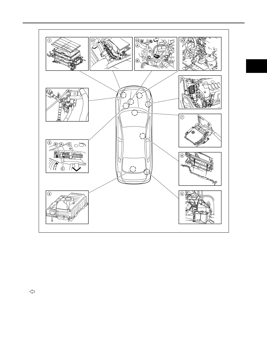
1.
Inverter with converter assembly
2.
Water pump with motor & bracket as-
sembly
3.
High voltage fuse and fusible link box
A: HV CONT MAIN fuse 10A
B: IGCT relay
C: IGCT fusible link 50A
D: DC/DC fusible link 120A
4.
HV battery
5.
Auxiliary battery
6.
Frame wire
7.
Hybrid vehicle control ECU
(located under heater box assembly)
8.
Brake ECU
9.
Electric compressor (For A/C)
10. A: Crankshaft position sensor
B: Axle
11. ECM
Vehicle front
ALCIA0009ZZ