Nissan Altima HL32 Hybrid. Manual - part 574
HYBRID TRANSAXLE
HBC-45
< FUNCTION DIAGNOSIS >
D
E
F
G
H
I
J
K
L
M
A
B
HBC
N
O
P
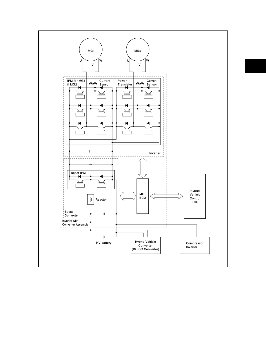
INVERTER ASSEMBLY : System Diagram
INFOID:0000000004211738
INVERTER ASSEMBLY : System Description
INFOID:0000000004211739
GENERAL
• The inverter converts the high-voltage direct current of the HV battery into three-phase alternating current for
driving MG1 and MG2.
• The activation of the power transistors is controlled by the hybrid vehicle control ECU, via the MG ECU. In
addition, the inverter transmits information that is needed for current control, such as the output amperage or
voltage, to the hybrid vehicle control ECU via the MG ECU.
• Together with MG1 and MG2, the inverter is cooled by the dedicated sub radiator of the coolant system that
is separate from that of the engine.
JMCIA0058GB