Nissan Altima HL32 Hybrid. Manual - part 457


  Index      Nissan     Nissan Altima HL32 Hybrid (2009 year) - Service and Repair Manual


Search            


Content   ..  455  456  457  458   ..


Nissan Altima HL32 Hybrid. Manual - part 457


FL-6

< ON-VEHICLE MAINTENANCE >

FUEL SYSTEM

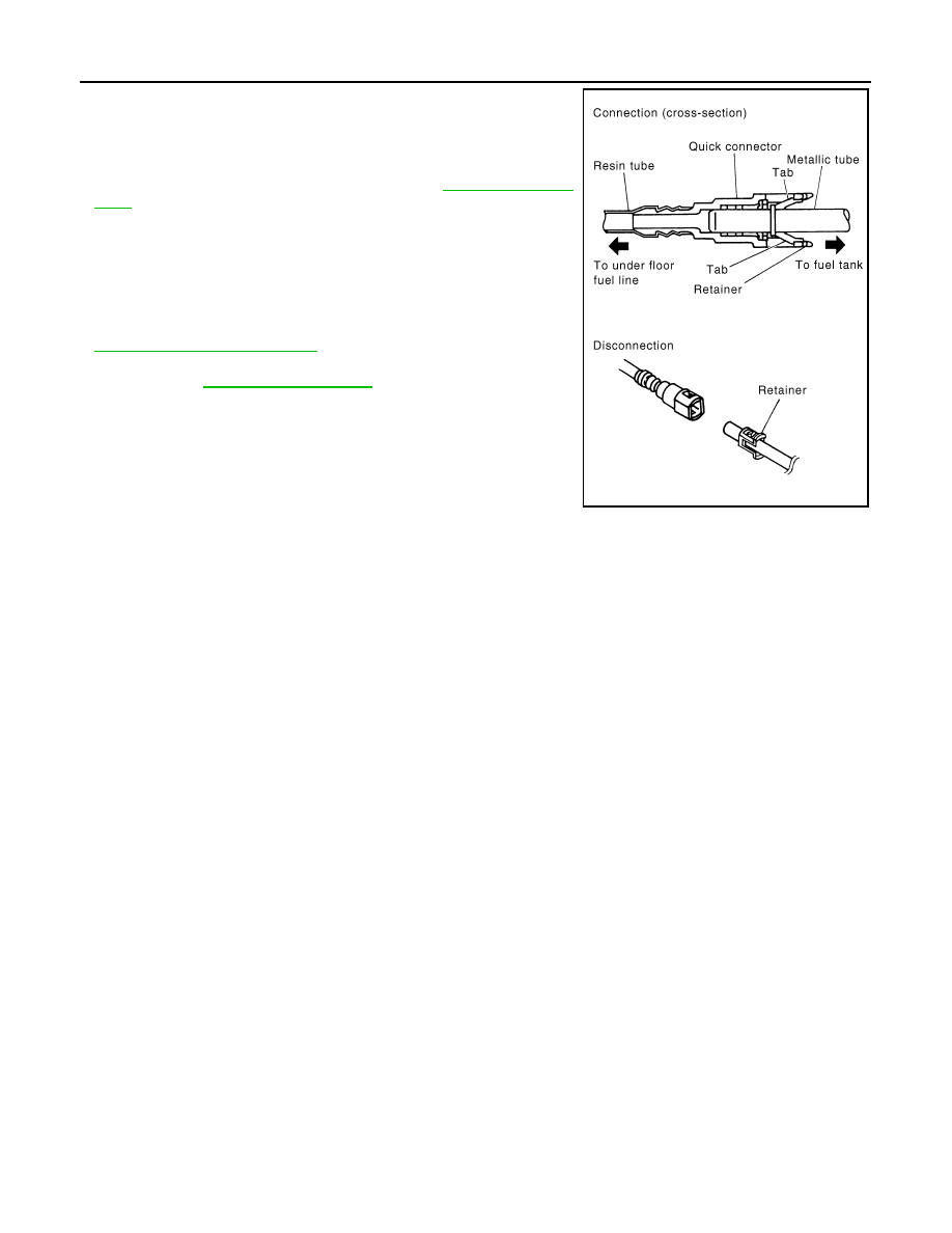
• After connecting the fuel tube quick connectors, make sure

the quick connectors are secure.

Check that the connector and resin tube do not contact any

adjacent parts.

- a) Apply fuel pressure to the fuel system then check for fuel

leaks at the fuel tube connections. Refer to 

EC-465, "Inspec-

tion"

.

- b) Turn on and rev the Hybrid System, then check for fuel

leaks at the fuel tube connections.

• After installing the tubes, run the Hybrid System and check

for fuel leaks at the connections.

• Use only a Genuine NISSAN fuel filler cap as a replacement. If

an incorrect fuel filler cap is used, the MIL may come on. 

• For servicing “Evaporative Emission System” parts, refer to

EC-65, "System Description"

• For servicing “On Board Refueling Vapor Recovery (ORVR)”

parts, refer to 

EC-396, "Description"

.

PBIC0199E

FUEL LEVEL SENSOR UNIT, FUEL FILTER AND FUEL PUMP ASSEMBLY

FL-7

< ON-VEHICLE REPAIR >

C

D

E

F

G

H

I

J

K

L

M

A

FL

N

P

O

ON-VEHICLE REPAIR

FUEL LEVEL SENSOR UNIT, FUEL FILTER AND FUEL PUMP ASSEMBLY

Exploded View

INFOID:0000000004211691

Removal and Installation

INFOID:0000000004211692

REMOVAL

WARNING:

Read “General Precautions” before working on the fuel system. 

Refer to 

GI-29, "General Precautions"

.

1. Unscrew the fuel filler cap to release the pressure inside the fuel tank.
2. Release the fuel pressure from the fuel lines. Refer to 

EC-465, "Inspection"

.

3. Disconnect the 12-volt battery negative terminal.
4. Remove the rear seat bottom. Refer to 

SE-22, "Removal and Installation"

.

5. Turn the four retainers 90

° in a clockwise direction and remove

the fuel pump inspection hole cover.

1.

Lock ring

2.

Fuel level sensor unit, fuel filter and 
fuel pump assembly

3.

O-ring

4.

Fuel Tank

AWBIA0563ZZ

LBIA0337E

FL-8

< ON-VEHICLE REPAIR >

FUEL LEVEL SENSOR UNIT, FUEL FILTER AND FUEL PUMP ASSEMBLY

6. Disconnect the fuel level sensor, fuel filter, and fuel pump

assembly electrical connector, EVAP hose quick connector, and

the fuel feed hose quick connector from the fuel level sensor

unit, fuel filter, and fuel pump assembly.

Remove the quick connector as follows:

• Hold the sides of the connector, push in tabs and pull out the

tube.

• If the connector and the tube are stuck together, push and pull

several times until they start to move. Then disconnect them

by pulling.

CAUTION:

• The tube can be removed when the tabs are completely

depressed. Do not twist it more than necessary.

• Do not use any tools to remove the quick connector.

• Keep the resin tube away from heat. Be especially careful

when welding near the tube.

• Prevent acid liquid such as battery electrolyte, etc. from getting on the resin tube.

• Do not bend or twist the tube during installation and removal.

• Only when the tube is replaced, remove the remaining retainer on the tube or fuel level sensor,

fuel filter, and fuel pump assembly.

• When the tube or fuel level sensor, fuel filter, and fuel pump assembly is replaced, also replace

the retainer with a new one (green colored retainer).

• To keep the connecting portion clean and to avoid dam-

age and foreign materials, cover them completely with

plastic bags or something similar.      

7. Remove the lock ring using a socket drive handle and Tool as

shown.

CAUTION:

• Discard the lock ring, do not reuse the lock ring.

• Discard the ring seal, do not reuse the ring seal.

LBIA0338E

SFE562A

PBIC0163E

Tool number

: KV991J0090 (J-46214)

WBIA0284E

FUEL LEVEL SENSOR UNIT, FUEL FILTER AND FUEL PUMP ASSEMBLY

FL-9

< ON-VEHICLE REPAIR >

C

D

E

F

G

H

I

J

K

L

M

A

FL

N

P

O

8. Remove the fuel level sensor, fuel filter, and fuel pump assem-

bly.

CAUTION:

• Do not bend the float arm during removal. 

• Discard the ring seal, do not reuse the ring seal.

INSPECTION AFTER REMOVAL

Inspect the fuel level sensor, fuel filter, and fuel pump for any defects and foreign materials. Replace as neces-

sary.

INSTALLATION

Installation is in the reverse order of removal.

• Install the fuel level sensor, fuel filter, and fuel pump assembly with

the fuel feed hose facing the front of the vehicle as shown. Use a

new ring seal.

• Connect the quick connector as follows:

- Check the connection for damage or any foreign materials.

- Align the connector with the tube, then insert the connector straight

into the tube until a click is heard.

• After the tube is connected, make sure the connection is secure by

performing the following checks:

- Pull the tube and the connector to make sure they are securely

connected.

LBIA0339E

LBIA0338E

PBIC1653E


Content   ..  455  456  457  458   ..