Nissan Altima HL32 Hybrid. Manual - part 455


  Index      Nissan     Nissan Altima HL32 Hybrid (2009 year) - Service and Repair Manual


Search            


Content   ..  453  454  455  456   ..


Nissan Altima HL32 Hybrid. Manual - part 455


FRONT DRIVE SHAFT

FAX-25

< DISASSEMBLY AND ASSEMBLY >

C

E

F

G

H

I

J

K

L

M

A

B

FAX

N

O

P

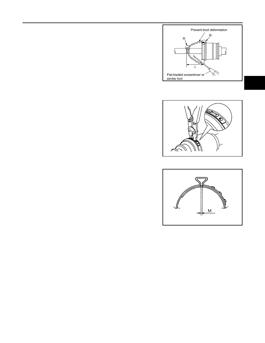
6. Install boot securely into grooves (indicated by * marks) as

shown.

CAUTION:

If there is grease on boot mounting surfaces (indicated by *

marks) of shaft and housing, boot may come off. Remove

all grease from surfaces.

7. Make sure boot installation length (L) is the specified length.

Insert a flat-bladed screwdriver or similar tool into the large end

of boot. Bleed air from boot to prevent boot deformation. 

CAUTION:

• Boot may break if boot installation length is less than standard value.

• Be careful that screwdriver tip does not contact inside surface of boot.

8. Install new large and small boot bands securely using Tool. 

NOTE:

Do not reuse boot bands.

CAUTION:

• Secure boot band so that dimension (M) meets specifica-

tion as shown. 

9. After installing housing and shaft, rotate boot to check whether or not the actual position is correct. If boot

position is not correct, remove old boot bands then reposition the boot and secure with new boot bands.

Support Bearing

1. Press support bearing into retaining bracket using a suitable tool.
2. Install support bearing onto slide joint assembly.
3. Install snap ring.
4. Install dust shield.

Damper

Boot installation length (L)

: 163 mm (6.42 in) 

Tool number

: KV40107300 (

)

SDIA1505E

RAC1133D

Dimension (M)

: 1.0 - 4.0 mm (0.039 - 0.157 in)

DSF0047D

FAX-26

< DISASSEMBLY AND ASSEMBLY >

FRONT DRIVE SHAFT

1. Use new damper bands for installation.
2. Install damper from stationary-joint side while holding it securely.

Dimension (A)

: 205 - 215 mm (8.07 - 8.46 in)

Dimension (B)

: 70 mm (2.76 in)

SFA313B

SERVICE DATA AND SPECIFICATIONS (SDS)

FAX-27

< SERVICE DATA AND SPECIFICATIONS (SDS) 

C

E

F

G

H

I

J

K

L

M

A

B

FAX

N

O

P

SERVICE DATA AND SPECIFICATIONS (SDS)

SERVICE DATA AND SPECIFICATIONS (SDS)

Wheel Bearing

INFOID:0000000004212414

Drive Shaft

INFOID:0000000004212415

Dynamic Damper

INFOID:0000000004212416

Axial end play limit

0.05 mm (0.002 in) or less

Joint type

Wheel side

Transaxle side

LH

RH

LH

RH

Grease quantity

170 - 190 g (6.00 - 6.70 oz)

134 - 144 g (4.73 - 5.08 oz)

Boots installed length (L)

163 mm (6.42 in)

167.9 mm (6.61 in)

189.30 (7.45 in)

SDIA1505E

(A)

205 - 215 mm (8.07 -8.46 in)

(B)

70 mm (2.76 in)

SFA313B

FL-1

ENGINE

C

D

E

F

G

H

I

J

K

L

M

SECTION 

FL

A

FL

N

O

P

CONTENTS

FUEL SYSTEM

PRECAUTION ...............................................

2

PRECAUTIONS ...................................................

2

Precaution for Supplemental Restraint System 
(SRS) "AIR BAG" and "SEAT BELT PRE-TEN-
SIONER" .................................................................
..

2

Precautions For High-Voltage System  ......................

2

Necessary for Steering Wheel Rotation After Bat-
tery Disconnect  .......................................................
..

2

PREPARATION ............................................

3

PREPARATION ...................................................

3

Special Service Tool  .................................................

3

Commercial Service Tool  ..........................................

3

ON-VEHICLE MAINTENANCE .....................

4

FUEL SYSTEM ....................................................

4

Inspection ..................................................................

4

Quick Connector  .......................................................

4

FUEL SYSTEM ....................................................

5

Checking Fuel Line ...................................................

5

General Precaution ...................................................

5

ON-VEHICLE REPAIR ..................................

7

FUEL LEVEL SENSOR UNIT, FUEL FILTER 
AND FUEL PUMP ASSEMBLY  .........................

7

Exploded View ..........................................................

7

Removal and Installation  ..........................................

7

Inspection ................................................................

10

FUEL TANK  ......................................................

11

Exploded View .........................................................

11

Removal and Installation  .........................................

11

Inspection ................................................................

14

SERVICE DATA AND SPECIFICATIONS 
(SDS) ............................................................

15

SERVICE DATA AND SPECIFICATIONS 
(SDS) .................................................................

15

Fuel Tank .................................................................

15


Content   ..  453  454  455  456   ..