Nissan Altima HL32 Hybrid. Manual - part 409


  Index      Nissan     Nissan Altima HL32 Hybrid (2009 year) - Service and Repair Manual


Search            


Content   ..  407  408  409  410   ..


Nissan Altima HL32 Hybrid. Manual - part 409


EXL-36

< FUNCTION DIAGNOSIS >

DIAGNOSIS SYSTEM (IPDM E/R)
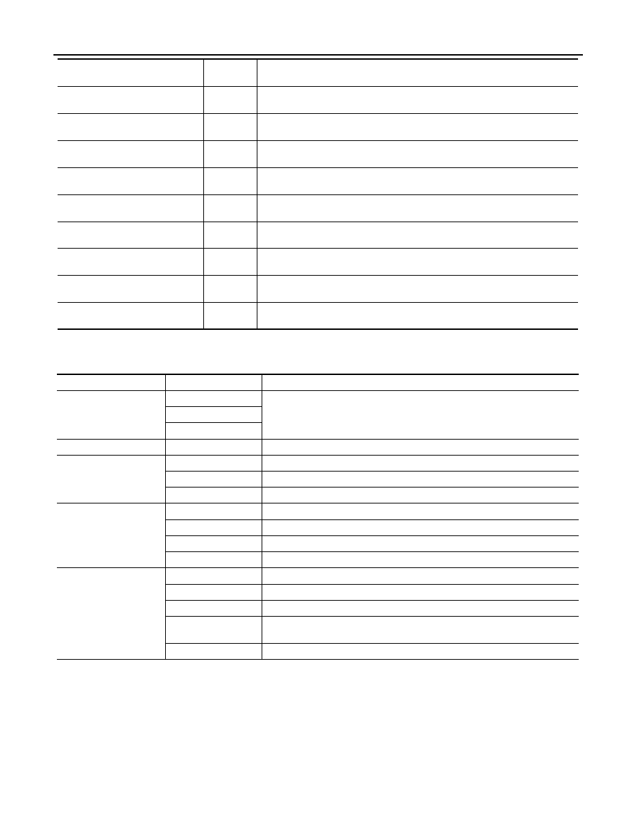
ACTIVE TEST

Test item

PUSH SW
[OFF/ON]

Displays the status of the push-button ignition switch judged by IPDM E/R.

DETENT SW
[OFF/ON]

Displays the status of the CVT device (detention switch) judged by IPDM E/R.

S/L RLY -REQ
[OFF/ON]

Displays the status of the electronic steering column lock relay request received 
from BCM via CAN communication.

S/L STATE
[LOCK/UNLK/UNKWN]

Displays the status of the electronic steering column lock judged by IPDM E/R.

DTRL REQ
[OFF]

NOTE:
This item is displayed, but cannot be monitored.

OIL P SW
[OPEN/CLOSE]

Displays the status of the oil pressure switch judged by IPDM E/R.

THFT HRN REQ
[OFF/ON]

Displays the status of the theft warning horn request signal received from BCM 
via CAN communication.

HORN CHIRP
[OFF/ON]

Displays the status of the horn reminder signal received from BCM via CAN com-
munication.

CRNRNG LMP REQ
[OFF]

NOTE:
This item is displayed, but cannot be monitored.

Monitor Item

[Unit]

MAIN SIG-

NALS

Description

Test item

Operation

Description

CORNERING LAMP

OFF

NOTE:
This item is displayed, but cannot be monitored.

LH

RH

HORN

ON

Operates horn relay for 20 ms.

FRONT WIPER

OFF

OFF

LO

Operates the front wiper relay.

HI

Operates the front wiper relay and front wiper high relay.

MOTOR FAN

1

OFF

2

Outputs 50% pulse duty signal (PWM signal) to the cooling fan control module.

3

Outputs 80% pulse duty signal (PWM signal) to the cooling fan control module.

4

Outputs 100% pulse duty signal (PWM signal) to the cooling fan control module.

EXTERNAL LAMPS

OFF

OFF

TAIL

Operates the tail lamp relay.

LO

Operates the headlamp low relay.

HI

Operates the headlamp low relay and ON/OFF the headlamp high relay at 1 sec-
ond intervals.

FOG

Operates the front fog lamp relay

POWER SUPPLY AND GROUND CIRCUIT

EXL-37

< COMPONENT DIAGNOSIS >

C

D

E

F

G

H

I

J

K

M

A

B

EXL

N

O

P

COMPONENT DIAGNOSIS

POWER SUPPLY AND GROUND CIRCUIT

BCM (BODY CONTROL MODULE)
BCM (BODY CONTROL MODULE) : Diagnosis Procedure

INFOID:0000000004501366

1.

 CHECK FUSE AND FUSIBLE LINK

Check if the following BCM fuse or fusible link are blown.

Is the fuse or fusible link blown?

YES

>> Replace the blown fuse or fusible link after repairing the affected circuit.

NO

>> GO TO 2

2.

 CHECK POWER SUPPLY CIRCUIT

1. Turn ignition switch OFF.

2. Disconnect BCM.

3. Check voltage between BCM harness connector and ground.

Is the measurement normal?

YES

>> GO TO 3

NO

>> Repair or replace harness.

3.

 CHECK GROUND CIRCUIT

Check continuity between BCM harness connector and ground.

Does continuity exist?

YES

>> Inspection End.

NO

>> Repair or replace harness.

BCM (BODY CONTROL MODULE) : Special Repair Requirement

INFOID:0000000004501367

1.

 REQUIRED WORK WHEN REPLACING BCM

Initialize control unit. Refer to CONSULT-III operation manual.

>> Work End.

IPDM E/R (INTELLIGENT POWER DISTRIBUTION MODULE ENGINE ROOM)

Terminal No.

Signal name

Fuse and fusible link No.

1

Battery power supply

J

11

10

Terminals

Voltage

(Approx.)

(+)

(

−)

BCM

Ground

Connector

Terminal

M16

1

Battery voltage

M17

11

ALCIA0025ZZ

BCM

Ground

Continuity

Connector

Terminal

M17

13

Yes

ALCIA0024ZZ

EXL-38

< COMPONENT DIAGNOSIS >

POWER SUPPLY AND GROUND CIRCUIT

IPDM E/R (INTELLIGENT POWER DISTRIBUTION MODULE ENGINE ROOM) : Di-
agnosis Procedure

INFOID:0000000004501370

1.

 CHECK FUSES AND FUSIBLE LINK

Check that the following IPDM E/R fuses or fusible link are not blown.

Is the fuse blown?

YES

>> Replace the blown fuse or fusible link after repairing the affected circuit.

NO

>> GO TO 2

2.

 CHECK POWER SUPPLY CIRCUIT

1. Turn ignition switch OFF.

2. Disconnect IPDM E/R.

3. Check voltage between IPDM E/R harness connector and

ground.

Is the measurement value normal?

YES

>> GO TO 3

NO

>> Repair or replace harness.

3.

 CHECK GROUND CIRCUIT

Check continuity between IPDM E/R harness connectors and

ground.

Does continuity exist?

YES

>> Inspection End.

NO

>> Repair or replace harness.

Terminal No.

Signal name

Fuses and fusible link No.

1, 2

Battery power supply

B, E, F

42

43

Terminals

Voltage (V)

(Approx.)

(+)

(

−)

IPDM E/R

Connector

Terminal

Ground

E16

1

Battery voltage

2

ALCIA0033ZZ

IPDM E/R

Ground

Continuity

Connector

Terminal

E18 (A)

12

Yes

E17 (B)

41

ALCIA0034ZZ

HEADLAMP (HI) CIRCUIT

EXL-39

< COMPONENT DIAGNOSIS >

C

D

E

F

G

H

I

J

K

M

A

B

EXL

N

O

P

HEADLAMP (HI) CIRCUIT

Description

INFOID:0000000004216388

The IPDM E/R (intelligent power distribution module engine room) controls the headlamp high relay based on

inputs from the BCM over the CAN communication lines. When the headlamp high relay is energized, power

flows through fuses 48 and 49, located in the IPDM E/R. Power then flows to the front combination lamps to

the headlamp high beam.

Component Function Check

INFOID:0000000004216389

1.

CHECK HEADLAMP (HI) OPERATION

WITHOUT CONTULT-III

1. Start IPDM E/R auto active test. Refer to 

PCS-14, "Diagnosis Description"

.

2. Check that the headlamp switches to the high beam.

NOTE:

HI/LO is repeated 1 second each when using the IPDM E/R auto active test.

CONSULT-III

1. Select "EXTERNAL LAMP" of IPDM E/R active test item.

2. With operating the test items, check that the headlamp switches to the high beam.

Does the headlamp switch to the high beam?

YES

>> Headlamp (HI) circuit is normal.

NO

>> Refer to 

EXL-39, "Diagnosis Procedure"

.

Diagnosis Procedure

INFOID:0000000004216390

1.

CHECK HEADLAMP (HI) FUSES

1. Turn the ignition switch OFF.

2. Check that the following fuses are not open.

Is the fuse open?

YES

>> Repair the harness and replace the fuse.

NO

>> GO TO 2

2.

CHECK HEADLAMP (HI) OUTPUT VOLTAGE

CONSULT-III ACTIVE TEST

1. Turn the ignition switch OFF.

2. Disconnect the front combination lamp connector.

3. Turn the ignition switch ON.

4. Select "EXTERNAL LAMP" of IPDM E/R active test item.

HI

: Headlamp switches to the high beam.

OFF

: Headlamp OFF

Unit

Location

Fuse

Capacity

Headlamp HI (LH) 

IPDM E/R

48

10A

Headlamp HI (RH) 

IPDM E/R

49

10A


Content   ..  407  408  409  410   ..