Nissan Altima HL32 Hybrid. Manual - part 381


  Index      Nissan     Nissan Altima HL32 Hybrid (2009 year) - Service and Repair Manual


Search            


Content   ..  379  380  381  382   ..


Nissan Altima HL32 Hybrid. Manual - part 381


EM-38

< ON-VEHICLE REPAIR >

[QR25DE]

ROCKER COVER

ROCKER COVER

Removal and Installation

INFOID:0000000004211248

REMOVAL

1. Disconnect the 12-volt battery negative terminal. 
2. Remove the engine cover.
3. Remove the front air duct. Refer to 

EM-24, "Removal and Installation"

.

4. Remove the blow-by hose.
5. Remove the two brake ECU nuts and set the brake ECU aside. Refer to 

BRC-198, "Removal and Installa-

tion"

.

6. Remove the RH engine mount torque rod. Refer to 

EM-71, "Removal and Installation"

.

7. Use a suitable tool to support the engine assembly.
8. Remove the RH engine support bracket. Refer to 

EM-71, "Removal and Installation"

.

9. Remove the RH engine mounting bracket. Refer to 

EM-71, "Removal and Installation"

.

10. Disconnect the PCV hose.
11. Remove the ignition coils. Refer to 

EM-34, "Removal and Installation"

.

12. Disconnect the fuel injectors and position the fuel injector harness aside.
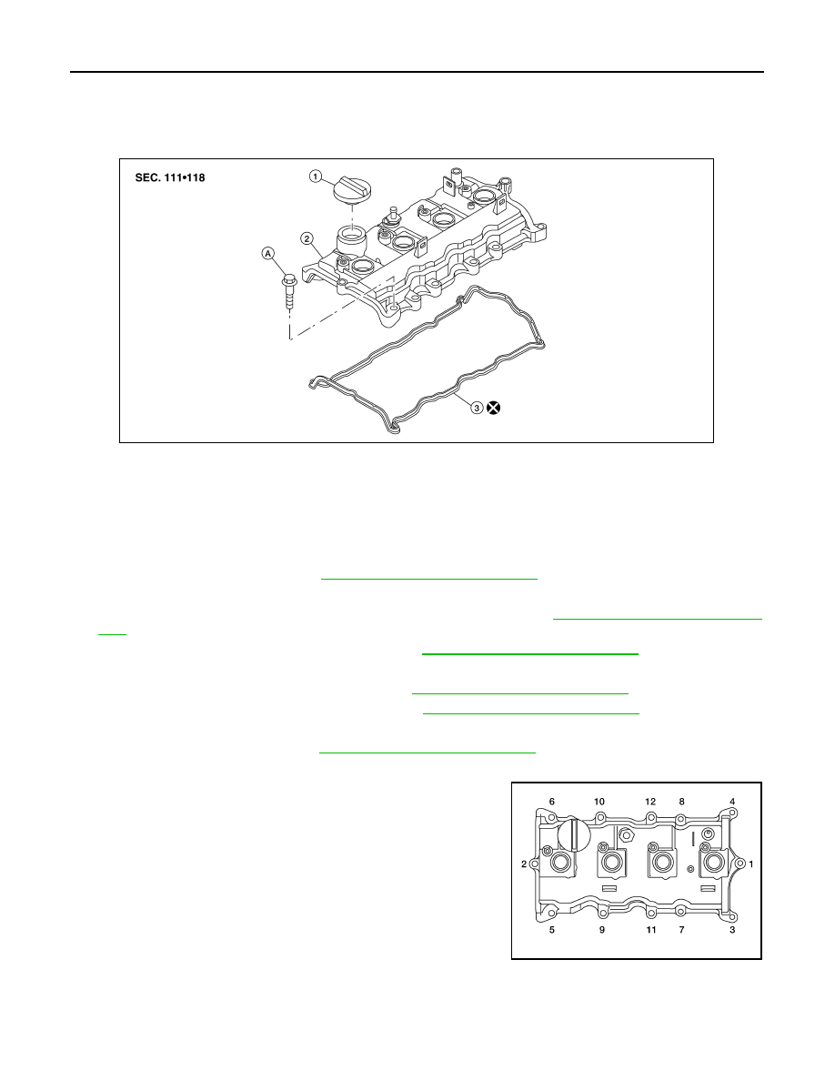
13. Loosen the bolts in the numerical order as shown using power

tool.

14. Remove the rocker cover and the rocker cover gasket. Discard

the rocker cover gasket.

CAUTION:

Do not reuse the rocker cover gasket.

15. Remove the oil filler cap if necessary, to transfer to the new

rocker cover.

INSTALLATION

1.

Oil filler cap

2.

Rocker cover

3.

Rocker cover gasket

A. Follow installation for tightening steps

ALBIA0189ZZ

ALBIA0190ZZ

ROCKER COVER

EM-39

< ON-VEHICLE REPAIR >

[QR25DE]

C

D

E

F

G

H

I

J

K

L

M

A

EM

N

P

O

1. Apply RTV Silicone Sealant to the joint part of the cylinder head

and camshaft bracket using the following the steps:

• Use Genuine Silicone RTV Sealant, or equivalent. Refer to 

GI-

15, "Recommended Chemical Products and Sealants"

.

a. Follow illustration (a) to apply sealant to joint part of No.1 cam-

shaft bracket and cylinder head.

b. Follow illustration (b) to apply sealant in a 90

° degree angle to

the illustration (a).

2. Install the rocker cover and the new rocker cover gasket.

• The rocker cover gasket must be securely installed in the groove in the rocker cover. 

3. Tighten the rocker cover bolts in two steps, in the numerical

order as shown.

4. Installation of the remaining components is in the reverse order of removal.

WBIA0164E

 Step 1

: 1.96 N·m (0.20 kg-m, 17 in-lb)

 Step 2

: 8.33 N·m (0.85 kg-m, 74 in-lb)

ALBIA0191ZZ

EM-40

< ON-VEHICLE REPAIR >

[QR25DE]

CAMSHAFT

CAMSHAFT

Removal and Installation

INFOID:0000000004211249

REMOVAL

1. Remove the rocker cover. Refer to 

EM-38, "Removal and Installation"

.

2. Remove the front right side tire and wheel. Refer to 

WT-62, "Adjustment"

.

3. Remove the RH splash shield using power tool.
4. Remove the drive belt. Refer to 

EM-14, "Removal and Installation of Drive Belt"

.

5. Remove the coolant overflow reservoir tank. 
6. Disconnect variable timing control solenoid and camshaft sensor harness connectors.
7. Remove camshaft sensor.
8. Remove camshaft sensor bracket.

AWBIA0591GB

1.

Camshaft bracket (No.1)

2.

Washer

3.

Front cover (partial view)

4.

Chain guide

5.

Chain tensioner

6.

O-ring(s)

7.

Chain tensioner spring

8.

Chain tensioner plunger

9.

IVT control solenoid valve

10. IVT control cover

11. Camshaft sprocket (EXH)

12. Camshaft sprocket (INT)

13. Valve lifter

14. Camshaft (EXH)

15. Camshaft (INT)

16. Camshaft brackets (EXH)

17. Camshaft brackets (INT)

18. Camshaft sensor bracket

A.

Follow installation for tightening steps

CAMSHAFT

EM-41

< ON-VEHICLE REPAIR >

[QR25DE]

C

D

E

F

G

H

I

J

K

L

M

A

EM

N

P

O

9. Loosen the IVT control cover bolts in the order as shown.

• Remove the IVT control cover by cutting the sealant using

Tool.

10. Set the No.1 cylinder at TDC on its compression stroke with the

following procedure:

a. Open the splash cover on RH under cover.
b. Rotate crankshaft pulley clockwise, and align mating marks for

TDC with timing indicator on front cover, as shown.

c. At the same time, make sure that the mating marks on camshaft

sprockets are lined up with the yellow links in the timing chain,

as shown.

• If not, rotate crankshaft pulley one more turn to line up the

mating marks to the yellow links, as shown.

11. Pull the timing chain guide out between the camshaft sprockets through front cover.

ALBIA0194ZZ

Tool number

: KV10111100 (J-37228)

WBIA0475E

KBIA0190E

KBIA0115E


Content   ..  379  380  381  382   ..