Nissan Altima HL32 Hybrid. Manual - part 379


  Index      Nissan     Nissan Altima HL32 Hybrid (2009 year) - Service and Repair Manual


Search            


Content   ..  377  378  379  380   ..


Nissan Altima HL32 Hybrid. Manual - part 379


EM-30

< ON-VEHICLE REPAIR >

[QR25DE]

EXHAUST MANIFOLD AND THREE WAY CATALYST

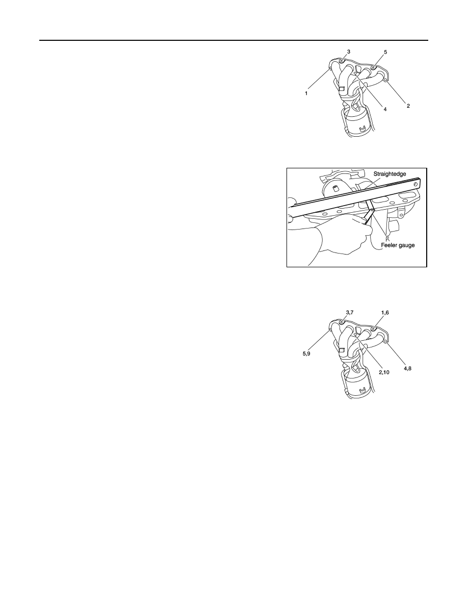
7. Loosen the nuts in the reverse order as shown, on the exhaust

manifold and three way catalyst assembly.

8. Remove the exhaust manifold and three way catalyst assembly

and gasket. Discard the gasket.

INSPECTION AFTER REMOVAL

Surface Distortion

• Use a reliable straightedge and feeler gauge to check the flatness

of exhaust manifold fitting surface.

INSTALLATION

Installation is in the reverse order of removal. 

Tightening Exhaust Manifold Nuts

• Tighten the nuts to specification in the numerical order as shown,

on the exhaust manifold and three way catalyst assembly. 

Installation of Air Fuel Ratio (A/F) Sensor 1

Clean the air fuel ratio (A/F) sensor 1 threads with the Tool, then apply the anti-seize lubricant to the threads

before installing the air fuel ratio (A/F) sensor 1.

CAUTION:

Do not over-tighten the air fuel ratio (A/F) sensor 1. Doing so may cause damage to the air fuel ratio (A/

F) sensor 1, resulting in a malfunction and the MIL coming on.

AWBIA0559ZZ

Limit

: 0.3 mm (0.012 in)

KBIA0046E

AWBIA0560ZZ

Tool number

: J-43897 - 18
: J-43897 - 12

OIL PAN AND OIL STRAINER

EM-31

< ON-VEHICLE REPAIR >

[QR25DE]

C

D

E

F

G

H

I

J

K

L

M

A

EM

N

P

O

OIL PAN AND OIL STRAINER

Removal and Installation

INFOID:0000000004211245

REMOVAL

WARNING:

To avoid the danger of being scalded, never drain the engine oil when the engine is hot.
1. Drain engine oil. Refer to 

LU-9, "Changing Engine Oil"

.

2. Remove the front exhaust tube. Refer to 

EX-6, "Removal and Installation"

.

3. Support the engine from above and underneath with suitable hoist and or jack.
4. Remove the front suspension assembly for clearance to remove the oil pan. Refer to 

FSU-14, "Removal

and Installation"

5. Remove the lower oil pan bolts in the order as shown, using

power tool.

AWBIA0012GB

1.

Oil level gauge guide

2.

Oil pan, upper

3.

Cylinder block

4.

Oil filter

5.

Oil strainer

6.

Drain plug

7.

Oil pan, lower

8.

Rear plate cover

9.

O-ring

A. To oil pan, lower

ALBIA0180ZZ

EM-32

< ON-VEHICLE REPAIR >

[QR25DE]

OIL PAN AND OIL STRAINER

6. Remove the lower oil pan using Tool.

NOTE:

Tap gently to cut sealant around the pan; do not damage the

mating surface using Tool.

7. Remove the oil strainer.
8. Remove rear plate cover, and four engine-to transaxle bolts, using power tool.

9. Loosen the upper oil pan bolts in the order shown to remove

upper oil pan, using power tool.

10. Remove upper oil pan using Tool.

NOTE:

Tap gently to cut sealant around the pan; do not damage the

mating surface using Tool.

INSPECTION AFTER REMOVAL

• Clean the oil strainer screen to remove all foreign material.

INSTALLATION

Installation is in the reverse order of removal.

• Apply Genuine Silicone RTV Sealant or equivalent to the upper oil

pan at the specified sealant bead diameter (A) as shown. Refer to

GI-15, "Recommended Chemical Products and Sealants"

.

CAUTION:

 Install two new O-rings in the upper oil pan.

Tool number

: KV10111100 (J-37228)

WBIA0475E

ALBIA0181ZZ

Tool number

: KV10111100 (J-37228)

WBIA0475E

Sealant bead diameter (A)

: 4.0 - 5.0 mm 
(0.157 - 0.197 in)

ALBIA0183ZZ

OIL PAN AND OIL STRAINER

EM-33

< ON-VEHICLE REPAIR >

[QR25DE]

C

D

E

F

G

H

I

J

K

L

M

A

EM

N

P

O

• Tighten the upper oil pan bolts in the order as shown.

• Apply Genuine Silicone RTV Sealant, or equivalent to the lower oil

pan as shown. Refer to 

GI-15, "Recommended Chemical Products

and Sealants"

.

• Tighten the lower oil pan bolts in the numerical order as shown.

CAUTION:

Wait at least 30 minutes after the oil pans are installed before

filling the engine with oil.

INSPECTION AFTER INSTALLATION

• Check for any engine oil leaks with the engine and inverter at operating temperature and running at idle.

ALBIA0184ZZ

Sealant bead diameter (A)

: 4.0 - 5.0 mm 
(0.157 - 0.197 in)

ALBIA0182ZZ

ALBIA0185ZZ


Content   ..  377  378  379  380   ..