Nissan Altima HL32 Hybrid. Manual - part 352


  Index      Nissan     Nissan Altima HL32 Hybrid (2009 year) - Service and Repair Manual


Search            


Content   ..  350  351  352  353   ..


Nissan Altima HL32 Hybrid. Manual - part 352


EC-392

< COMPONENT DIAGNOSIS >

[QR25DE]

IGNITION SIGNAL

YES

>> GO TO 6.

NO

>> Replace condenser.

6.

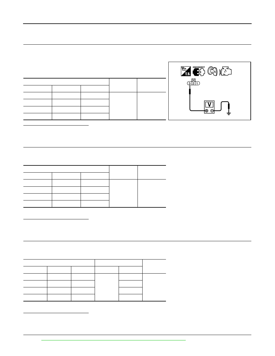
CHECK IGNITION COIL POWER SUPPLY CIRCUIT-V

1. Reconnect all harness connectors disconnected.

2. Disconnect ignition coil harness connector.

3. Turn ignition switch ON.

4. Check the voltage between ignition coil harness connector and

ground.

Is the inspection result normal?

YES

>> GO TO 7.

NO

>> Repair open circuit or short to ground or short to power in harness or connectors.

7.

CHECK IGNITION COIL GROUND CIRCUIT FOR OPEN AND SHORT

1. Turn ignition switch OFF.

2. Check the continuity between ignition coil harness connector and ground.

3. Also check harness for short to power.
Is the inspection result normal?

YES

>> GO TO 8.

NO

>> Repair open circuit or short to ground or short to power in harness or connectors.

8.

CHECK IGNITION COIL OUTPUT SIGNAL CIRCUIT FOR OPEN AND SHORT

1. Disconnect ECM harness connector.

2. Check the continuity between ECM harness connector and ignition coil harness connector.

3. Also check harness for short to ground and short to power.
Is the inspection result normal?

YES

>> GO TO 9.

NO

>> Repair open circuit or short to ground or short to power in harness or connectors.

9.

CHECK IGNITION COIL WITH POWER TRANSISTOR

Refer to 

EC-393, "Component Inspection (Ignition Coil with Power Transistor)"

.

Ignition coil

Ground

Voltage

Cylinder

Connector

Terminal

1

F34

3

Ground

Battery voltage

2

F35

3

3

F36

3

4

F37

3

PBIB0138E

Ignition coil

Ground

Continuity

Cylinder

Connector

Terminal

1

F34

2

Ground

Existed

2

F35

2

3

F36

2

4

F37

2

Ignition coil

ECM

Continuity

Cylinder

Connector

Terminal

Connector

Terminal

1

F34

1

F14

11

Existed

2

F35

1

10

3

F36

1

9

4

F37

1

21

IGNITION SIGNAL

EC-393

< COMPONENT DIAGNOSIS >

[QR25DE]

C

D

E

F

G

H

I

J

K

L

M

A

EC

N

P

O

Is the inspection result normal?

YES

>> GO TO 10.

NO

>> Replace malfunctioning ignition coil with power transistor.

10.

CHECK INTERMITTENT INCIDENT

Refer to 

GI-42, "Intermittent Incident"

.

>> INSPECTION END

Component Inspection (Ignition Coil with Power Transistor)

INFOID:0000000004211644

1.

CHECK IGNITION COIL WITH POWER TRANSISTOR-I

1. Turn ignition switch OFF.

2. Disconnect ignition coil harness connector.

3. Check resistance between ignition coil terminals as follows.

Is the inspection result normal?

YES

>> GO TO 2.

NO

>> Replace malfunctioning ignition coil with power transis-

tor.

2.

CHECK IGNITION COIL WITH POWER TRANSISTOR-II

CAUTION:

Do the following procedure in the place where ventilation is good without the combustible.

1. Turn ignition switch OFF.

2. Remove fuel pump fuse in IPDM E/R to release fuel pressure.

NOTE:

Do not use CONSULT-III to release fuel pressure, or fuel pressure applies again during the following pro-

cedure.

3. Turn ignition switch ON (READY).

4. Depress accelerator pedal and keep it.

5. After engine stalls, check DTC.

If DTC is detected, erase DTC and go to next steps.

If DTC is not detected, go to next steps.

6. Turn ignition switch OFF.

7. Remove all ignition coil harness connectors to avoid the electrical discharge from the ignition coils.

8. Remove ignition coil and spark plug of the cylinder to be checked.

9. Repeat steps 3 to 5 for two or three times to remove combustion gas in the cylinder.

10. Connect spark plug and harness connector to ignition coil.

11. Fix ignition coil using a rope etc. with gap of 13 - 17 mm (0.52 -

0.66 in) between the edge of the spark plug and grounded metal

portion as shown in the figure.

12. Turn ignition switch ON (READY).

13. Depress accelerator pedal for about 3 seconds, and check

whether spark is generated between the spark plug and the

grounded metal portion.

CAUTION:

• Do not approach to the spark plug and the ignition coil

within 50 cm (19.7 in). Be careful not to get an electrical

shock while checking, because the electrical discharge voltage becomes 20kV or more.

• It might cause to damage the ignition coil if the gap of more than 17 mm (0.66 in) is taken.

Terminals

Resistance 

Ω [at 25°C (77°F)]

1 and 2

Except 0 or 

1 and 3

Except 0

2 and 3

PBIB0847E

Spark should be generated.

JMBIA0066GB

EC-394

< COMPONENT DIAGNOSIS >

[QR25DE]

IGNITION SIGNAL

NOTE:

When the gap is less than 13 mm (0.52 in), the spark might be generated even if the coil is mal-

functioning.

Is the inspection result normal?

YES

>> INSPECTION END

NO

>> Replace malfunctioning ignition coil with power transistor.

Component Inspection (Condenser-2)

INFOID:0000000004211645

1.

CHECK CONDENSER-2

1. Turn ignition switch OFF.

2. Disconnect condenser-2 harness connector.

3. Check resistance between condenser-2 terminals as follows.

Is the inspection result normal?

YES

>> INSPECTION END

NO

>> Replace condenser-2.

Terminals

Resistance

1 and 2

Above 1 M

Ω [at 25°C (77°F)]

PBIB0794E

MALFUNCTION INDICATOR LAMP

EC-395

< COMPONENT DIAGNOSIS >

[QR25DE]

C

D

E

F

G

H

I

J

K

L

M

A

EC

N

P

O

MALFUNCTION INDICATOR LAMP

Description

INFOID:0000000004211646

The Malfunction Indicator Lamp (MIL) is located on the combination

meter.

The MIL will light up when the ignition switch is turned ON without

the engine running. This is a bulb check.

When the engine is started, the MIL should go off. If the MIL remains

on, the on board diagnostic system has detected an engine system

malfunction.

For details, refer to 

EC-395, "Diagnosis Procedure"

.

Component Function Check

INFOID:0000000004211647

1.

CHECK MIL FUNCTION

1. Turn ignition switch ON.

2. Make sure that MIL lights up.
Is the inspection result normal?

YES

>> INSPECTION END

NO

>> Go to 

EC-395, "Diagnosis Procedure"

.

Diagnosis Procedure

INFOID:0000000004211648

1.

CHECK DTC

Check that DTC U1000 or U1001 is not displayed.
Is the inspection result normal?

YES

>> GO TO 2.

NO

>> Perform trouble diagnosis for DTC U1000, U1001. Refer to 

EC-119, "Diagnosis Procedure"

.

2.

CHECK DTC WITH COMBINATION METER

Refer to 

MWI-72, "DTC Index"

.

Is the inspection result normal?

YES

>> GO TO 3.

NO

>> Repair or replace.

3.

CHECK INTERMITTENT INCIDENT

Refer to 

GI-42, "Intermittent Incident"

.

Is the inspection result normal?

YES

>> Replace combination meter.

NO

>> Repair or replace.

SEF217U


Content   ..  350  351  352  353   ..