Nissan Altima HL32 Hybrid. Manual - part 350


  Index      Nissan     Nissan Altima HL32 Hybrid (2009 year) - Service and Repair Manual


Search            


Content   ..  348  349  350  351   ..


Nissan Altima HL32 Hybrid. Manual - part 350


EC-384

< COMPONENT DIAGNOSIS >

[QR25DE]

COOLING FAN

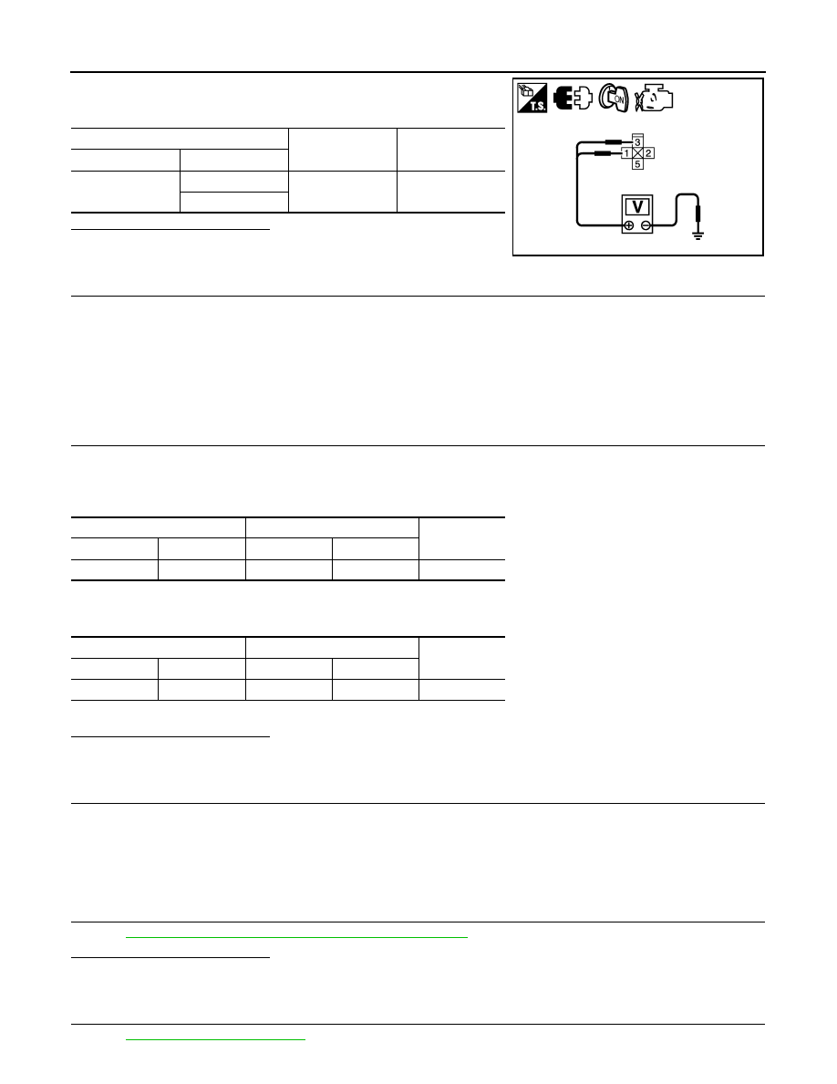
4. Check the voltage between cooling fan relay harness connector

and ground.

Is the inspection result normal?

YES

>> GO TO 9.

NO

>> GO TO 8.

8.

DETECT MALFUNCTIONING PART

Check the following.

• IPDM E/R harness connector E18

• 50A fusible link (letter O)

• Harness for open or short between cooling fan relay-1 and fuse

• Harness for open or short between cooling fan relay-1 and IPDM E/R

>> Repair open circuit or short to ground or short to power in harness or connectors.

9.

CHECK COOLING FAN CONTROL MODULE POWER SUPPLY CIRCUIT-III

1. Turn ignition switch OFF.

2. Disconnect IPDM E/R harness connector E17.

3. Check the continuity between cooling fan relay-1 harness connector and IPDM E/R harness connector.

4. Check the continuity between cooling fan relay harness connector and cooling fan control module harness

connector.

5. Also check harness for short to ground and short to power.
Is the inspection result normal?

YES

>> GO TO 11.

NO

>> GO TO 10.

10.

DETECT MALFUNCTIONING PART

Check the following.

• Harness connector E81, E207

• Harness for open or short between cooling fan relay-1 and cooling fan control module

>> Repair open circuit or short to ground or short to power in harness or connectors.

11.

CHECK COOLING FAN RELAY-1

Refer to 

EC-385, "Component Inspection (Cooling Fan Relay)"

.

Is the inspection result normal?

YES

>> GO TO 12.

NO

>> Replace cooling fan relay-1.

12.

CHECK INTERMITTENT INCIDENT

Perform 

GI-42, "Intermittent Incident"

.

Cooling fan relay-1

Ground

Voltage

Connector

Terminal

E82

1

Ground

Battery voltage

3

JMBIA1646ZZ

Cooling fan relay-1

IPDM E/R

Continuity

Connector

Terminal

Connector

Terminal

E82

2

E17

42

Existed

Cooling fan relay-1

Cooling fan control module

Continuity

Connector

Terminal

Connector

Terminal

E82

5

E231

3

Existed

COOLING FAN

EC-385

< COMPONENT DIAGNOSIS >

[QR25DE]

C

D

E

F

G

H

I

J

K

L

M

A

EC

N

P

O

Is the inspection result normal?

YES

>> Replace IPDM E/R.

NO

>> Repair or replace harness connectors.

Component Inspection (Cooling Fan Motor)

INFOID:0000000004211634

1.

CHECK COOLING FAN MOTOR

1. Turn ignition switch OFF.

2. Disconnect cooling fan control module harness connectors E232, E233.

3. Supply cooling fan control module terminals with battery voltage and check operation.

Is the inspection result normal?

YES

>> INSPECTION END

NO

>> Replace cooling fan motor.

Component Inspection (Cooling Fan Relay)

INFOID:0000000004211635

1.

CHECK COOLING FAN RELAY-1

1. Turn ignition switch OFF.

2. Remove cooling fan relay-1.

3. Check the continuity between cooling fan relay-1 terminals

under the following conditions.

Is the inspection result normal?

YES

>> INSPECTION END

NO

>> Replace cooling fan relay.

Cooling fan control module

Operation

Motor

Connector

Terminal

(+)

(–)

1

E232

4

5

Cooling fan operates.

2

E233

6

7

Terminals

Conditions

Continuity

3 and 5

12V direct current supply between terminals 1 and 2

Existed

No current supply

Not existed

SEF090M

EC-386

< COMPONENT DIAGNOSIS >

[QR25DE]

FUEL PUMP

FUEL PUMP

Description

INFOID:0000000004211636

*: ECM determines the start signal status by the signals of engine speed and battery voltage.

The ECM activates the fuel pump for several seconds after the ignition switch is turned ON to improve engine

start ability. If the ECM receives a engine speed signal from the camshaft position sensor (PHASE), it knows

that the engine is rotating, and causes the pump to operate. If the engine speed signal is not received when

the ignition switch is ON, the engine stalls. The ECM stops pump operation and prevents battery discharging,

thereby improving safety. The ECM does not directly drive the fuel pump. It controls the ON/OFF fuel pump

relay, which in turn controls the fuel pump.

Component Function Check

INFOID:0000000004211637

1.

CHECK FUEL PUMP FUNCTION

1. Turn ignition switch ON.

2. Pinch fuel feed hose (1) with two fingers.

Is the inspection result normal?

YES

>> INSPECTION END

NO

>>

EC-386, "Diagnosis Procedure"

.

Diagnosis Procedure

INFOID:0000000004211638

1.

CHECK FUEL PUMP POWER SUPPLY CIRCUIT-I

1. Turn ignition switch OFF.

2. Disconnect ECM harness connector.

3. Turn ignition switch ON.

Sensor

Input signal to ECM

ECM Function

Actuator

Crankshaft position sensor (POS)
Camshaft position sensor (PHASE)

Engine speed*

Fuel pump control

Fuel pump relay

Fuel pump

Battery

Battery voltage*

Condition

Fuel pump operation

Ignition switch is turned to ON.

Operates for 1 second.

Engine running and cranking

Operates.

When engine is stopped

Stops in 1.5 seconds.

Except as shown above

Stops.

: Vehicle front

Fuel pressure pulsation should be felt on the fuel feed 
hose for 1 second after ignition switch is turned ON.

ALBIA0151ZZ

FUEL PUMP

EC-387

< COMPONENT DIAGNOSIS >

[QR25DE]

C

D

E

F

G

H

I

J

K

L

M

A

EC

N

P

O

4. Check the voltage between ECM harness connector and

ground.

Is the inspection result normal?

YES

>> GO TO 4.

NO

>> GO TO 2.

2.

CHECK FUEL PUMP POWER SUPPLY CIRCUIT-II

1. Turn ignition switch OFF.

2. Disconnect IDPDM E/R harness connector F10.

3. Check the continuity between IPDM E/R harness connector and ECM harness connector.

Is the inspection result normal?

YES

>> GO TO 3.

NO

>> Repair open circuit or short to ground or short to power in harness or connectors.

3.

CHECK CONDENSER-1 POWER SUPPLY CIRCUIT-I

1. Reconnect all harness connectors disconnected.

2. Disconnect condenser-1 harness connector.

3. Turn ignition switch ON.

4. Check the voltage between condenser-1 harness connector and

ground.

Is the inspection result normal?

YES

>> GO TO 5.

NO

>> GO TO 4.

4.

CHECK 15A FUSE

1. Turn ignition switch OFF.

2. Disconnect 15A fuse (No. 32) from IPDM E/R.

3. Check 15A fuse.
Is the inspection result normal?

YES

>> GO TO 6.

NO

>> Replace fuse.

5.

CHECK CONDENSER-1 POWER SUPPLY CIRCUIT-II

1. Disconnect IPDM E/R harness connector E18.

2. Check the continuity between IPDM E/R harness connector and condenser-1 harness connector.

3. Also check harness for short to ground and short to power.

ECM

Ground

Voltage

Connector

Terminal

F14

14

Ground

Battery voltage

JMBIA1618ZZ

ECM

IPDM E/R

Continuity

Connector

Terminal

Connector

Terminal

F14

14

F10

77

Existed

Condenser-1

Ground

Voltage

Connector Terminal

B17

1

Ground

Battery voltage should exist for 1 second after ig-
nition switch is turned ON.

PBIB0624E

IPDM E/R

Condenser-1

Continuity

Connector

Terminal

Connector

Terminal

F18

13

B17

1

Existed


Content   ..  348  349  350  351   ..