Nissan Altima HL32 Hybrid. Manual - part 346
EC-368
< COMPONENT DIAGNOSIS >
[QR25DE]
P2135 TP SENSOR
NO
>> Repair or replace ground connection.
2.
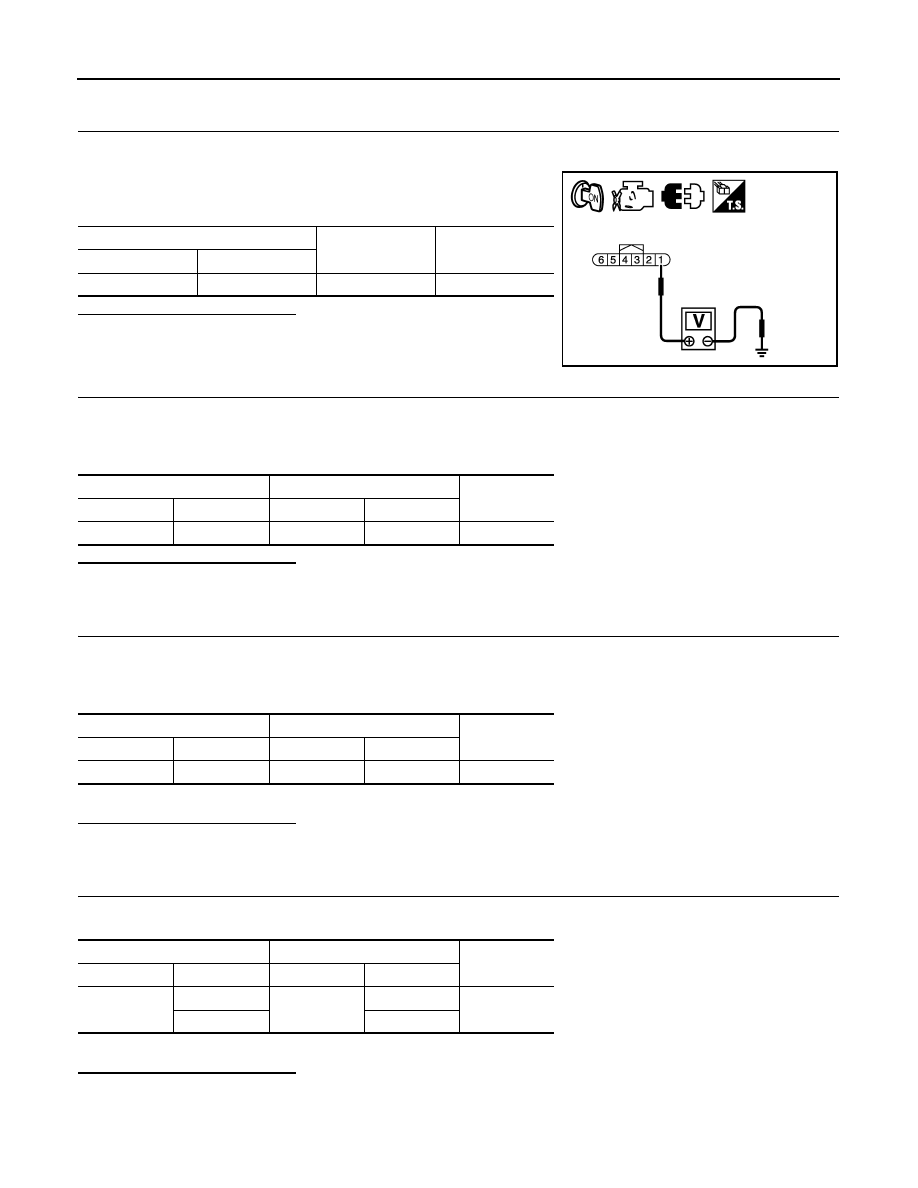
CHECK THROTTLE POSITION SENSOR POWER SUPPLY CIRCUIT-I
1. Disconnect electric throttle control actuator harness connector.
2. Turn ignition switch ON.
3. Check the voltage between electric throttle control actuator har-
ness connector and ground.
Is the inspection result normal?
YES
>> GO TO 4.
NO
>> GO TO 3.
3.
CHECK THROTTLE POSITION SENSOR POWER SUPPLY CIRCUIT-II
1. Turn ignition switch OFF.
2. Disconnect ECM harness connector.
3. Check the continuity between electric throttle control actuator harness connector and ground.
Is the inspection result normal?
YES
>> GO TO 4.
NO
>> Repair open circuit.
4.
CHECK THROTTLE POSITION SENSOR GROUND CIRCUIT FOR OPEN AND SHORT
1. Turn ignition switch OFF.
2. Disconnect ECM harness connector.
3. Check the continuity between electric throttle control actuator harness connector and ground.
4. Also check harness for short to ground and short to power.
Is the inspection result normal?
YES
>> GO TO 5.
NO
>> Repair open circuit or short to ground or short to power in harness or connectors.
5.
CHECK THROTTLE POSITION SENSOR INPUT SIGNAL CIRCUIT FOR OPEN AND SHORT
1. Check the continuity between electric throttle control actuator harness connector and ground.
2. Also check harness for short to ground and short to power.
Is the inspection result normal?
YES
>> GO TO 6.
NO
>> Repair open circuit or short to ground or short to power in harness or connectors.
Electric throttle control actuator
Ground
Voltage
Connector
Terminal
F57
1
Ground
Approx. 5V
JMBIA1584ZZ
Electric throttle control actuator
ECM
Continuity
Connector
Terminal
Connector
Terminal
F57
1
F13
47
Existed
Electric throttle control actuator
ECM
Continuity
Connector
Terminal
Connector
Terminal
F57
4
F13
36
Existed
Electric throttle control actuator
ECM
Continuity
Connector
Terminal
Connector
Terminal
F57
2
F13
37
Existed
3
38