Nissan Altima HL32 Hybrid. Manual - part 311
EC-228
< COMPONENT DIAGNOSIS >
[QR25DE]
P0172 FUEL INJECTION SYSTEM FUNCTION
P0172 FUEL INJECTION SYSTEM FUNCTION
DTC Logic
INFOID:0000000004211463
DTC DETECTION LOGIC
With the Air/Fuel Mixture Ratio Self-Learning Control, the actual mixture ratio can be brought closely to the
theoretical mixture ratio based on the mixture ratio feedback signal from the A/F sensors 1. The ECM calcu-
lates the necessary compensation to correct the offset between the actual and the theoretical ratios.
In case the amount of the compensation value is extremely large (The actual mixture ratio is too rich.), the
ECM judges the condition as the fuel injection system malfunction and lights up the MIL (2 trip detection logic).
DTC CONFIRMATION PROCEDURE
1.
PRECONDITIONING
If DTC Confirmation Procedure has been previously conducted, always perform the following before conduct-
ing the next test.
1. Turn ignition switch OFF and wait at least 10 seconds.
2. Turn ignition switch ON.
3. Turn ignition switch OFF and wait at least 10 seconds.
>> GO TO 2.
2.
PERFORM DTC CONFIRMATION PROCEDURE-II
1. Clear the mixture ratio self-learning value. Refer to
EC-18, "MIXTURE RATIO SELF-LEARNING VALUE
CLEAR : Special Repair Requirement"
.
2. Activate “INSPECTION MODE 1” (
) to start engine, and let engine idle for at least 5 minutes.
3. Check 1st trip DTC.
Is 1st trip DTC detected?
YES
>> Go to
NO
>> GO TO 3.
3.
PERFORM DTC CONFIRMATION PROCEDURE-III
1. Turn ignition switch OFF and wait at least 10 seconds.
2. Turn ignition switch ON (READY).
3. Maintain the following conditions for at least 10 consecutive minutes. Hold the accelerator pedal as steady
as possible.
CAUTION:
Always drive vehicle at a safe speed.
4. Check 1st trip DTC.
Is 1st trip DTC detected?
YES
>> Go to
NO
>> INSPECTION END
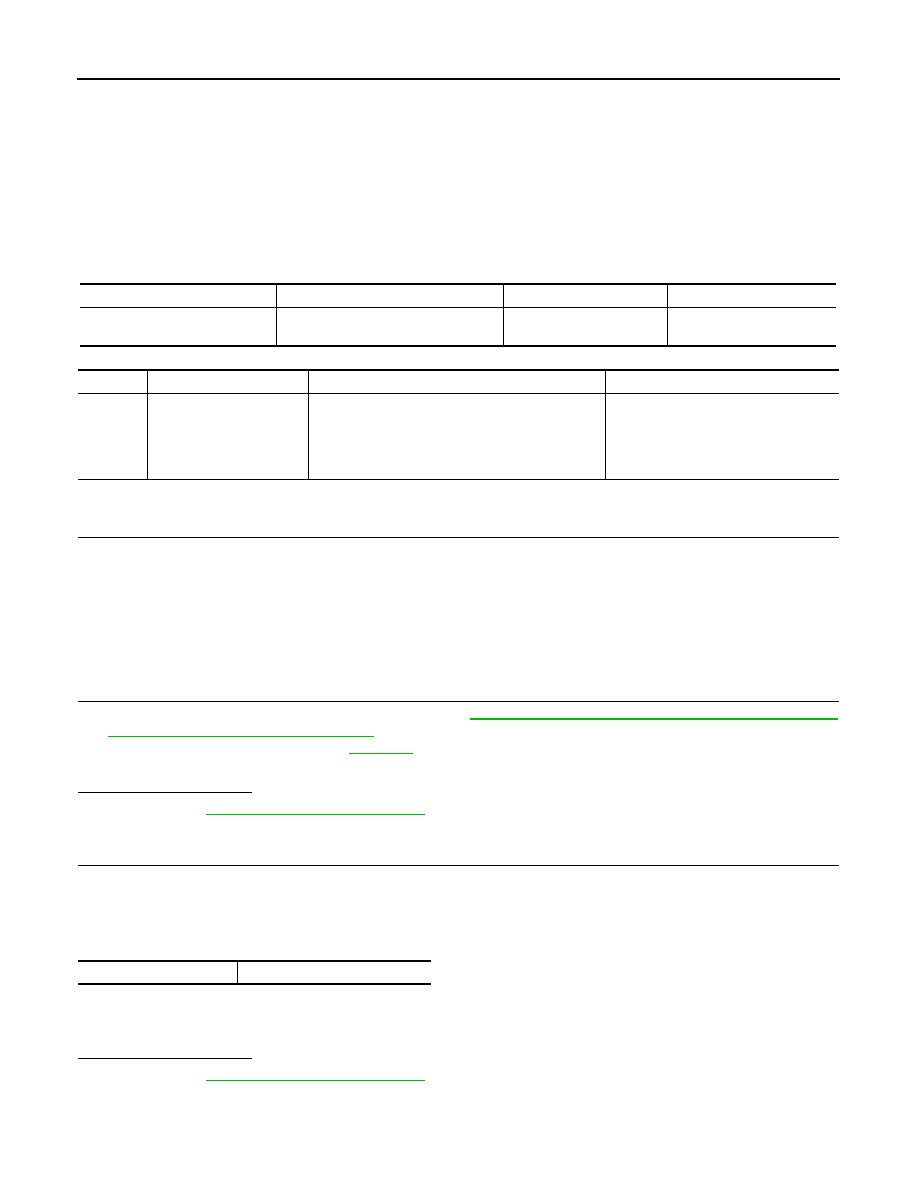
Sensor
Input signal to ECM
ECM function
Actuator
A/F sensor 1
Density of oxygen in exhaust gas
(Mixture ratio feedback signal)
Fuel injection control
Fuel injector
DTC No.
Trouble diagnosis name
DTC detecting condition
Possible cause
P0172
Fuel injection system too
rich
• Fuel injection system does not operate properly.
• The amount of mixture ratio compensation is too
large. (The mixture ratio is too rich.)
• A/F sensor 1
• Fuel injector
• Exhaust gas leaks
• Incorrect fuel pressure
• Mass air flow sensor
VECL SPEED SE
80 - 120 km/h (50 mph - 75 mph)