Nissan Altima HL32 Hybrid. Manual - part 297


  Index      Nissan     Nissan Altima HL32 Hybrid (2009 year) - Service and Repair Manual


Search            


Content   ..  295  296  297  298   ..


Nissan Altima HL32 Hybrid. Manual - part 297


EC-172

< COMPONENT DIAGNOSIS >

[QR25DE]

P0125 ECT SENSOR

P0125 ECT SENSOR

Description

INFOID:0000000004362538

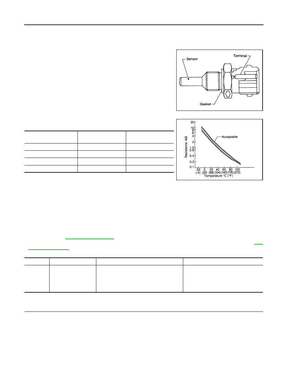
The engine coolant temperature sensor is used to detect the engine

coolant temperature. The sensor modifies a voltage signal from the

ECM. The modified signal returns to the ECM as the engine coolant

temperature input. The sensor uses a thermistor which is sensitive to

the change in temperature. The electrical resistance of the ther-

mistor decreases as temperature increases.

<Reference data>

*: These data are reference values and are measured between ECM terminal 46
(Engine coolant temperature sensor) and ground.

CAUTION:

Do not use ECM ground terminals when measuring input/output voltage. Doing so may result in damage to the ECM's transis-
tor. Use a ground other than ECM terminals, such as the ground.

DTC Logic

INFOID:0000000004211411

DTC DETECTION LOGIC

NOTE:

• If DTC P0125 is displayed with P0117 or P0118, first perform the trouble diagnosis for DTC P0117 or

P0118. Refer to 

EC-166, "DTC Logic"

.

• If DTC P0125 is displayed with P0116, first perform the trouble diagnosis for DTC P0116. Refer to 

EC-

164, "DTC Logic"

.

DTC CONFIRMATION PROCEDURE

1.

PRECONDITIONING

If DTC Confirmation Procedure has been previously conducted, always perform the following before conduct-

ing the next test.

1. Turn ignition switch OFF and wait at least 10 seconds.

2. Turn ignition switch ON.

3. Turn ignition switch OFF and wait at least 10 seconds.

>> GO TO 2.

SEF594K

Engine coolant temperature

°C (°F)]

Voltage* (V)

Resistance (k

–10 (14)

4.4

7.0 - 11.4

20 (68)

3.5

2.37 - 2.63

50 (122)

2.2

0.68 - 1.00

90 (194)

0.9

0.236 - 0.260

SEF012P

DTC No.

Trouble diagnosis name

DTC detecting condition

Possible cause

P0125

Insufficient engine cool-
ant temperature for 
closed loop fuel control

• Voltage sent to ECM from the sensor is not 

practical, even when some time has passed 
after starting the engine.

• Engine coolant temperature is insufficient for 

closed loop fuel control.

• Harness or connectors

(High resistance in the circuit)

• Engine coolant temperature sensor
• Thermostat

P0125 ECT SENSOR

EC-173

< COMPONENT DIAGNOSIS >

[QR25DE]

C

D

E

F

G

H

I

J

K

L

M

A

EC

N

P

O

2.

CHECK ENGINE COOLANT TEMPERATURE SENSOR FUNCTION

With CONSULT-III

1. Turn ignition switch ON.

2. Select “DATA MONITOR” mode with CONSULT-III.

3. Check that “COOLAN TEMP/S” is above 5

°C (41°F).

With GST

Follow the procedure “With CONSULT-III” above.
Is it above 5

°C (41°F)?

YES

>> INSPECTION END

NO

>> GO TO 3.

3.

PERFORM DTC CONFIRMATION PROCEDURE

With CONSULT-III

1. Activate “INSPECTION MODE 1” (

HBC-104

) to start engine, and run engine for 65 minutes at idle speed.

2. Check 1st trip DTC.

If “COOLAN TEMP/S” increases to more than 5

°C (41°F) within 65 minutes, turn ignition switch OFF

because the test result will be OK.

CAUTION:

Be careful not to overheat engine.

With GST

Follow the procedure “With CONSULT-III” above.
Is 1st trip DTC detected?

YES

>>

EC-173, "Diagnosis Procedure"

NO

>> INSPECTION END

Diagnosis Procedure

INFOID:0000000004211412

1.

CHECK GROUND CONNECTION

1. Turn ignition switch OFF.

2. Check ground connection E9. Refer to Ground Inspection in 

GI-45, "Circuit Inspection"

.

Is the inspection result normal?

YES

>> GO TO 2.

NO

>> Repair or replace ground connection.

2.

CHECK ENGINE COOLANT TEMPERATURE SENSOR

Refer to 

EC-173, "Component Inspection"

.

Is the inspection result normal?

YES

>> GO TO 3.

NO

>> Replace engine coolant temperature sensor.

3.

CHECK THERMOSTAT OPERATION

When the engine is cold [lower than 70

°C (158°F)] condition, grasp lower radiator hose and confirm the engine

coolant does not flow.
Is the inspection result normal?

YES

>> GO TO 4.

NO

>> Repair or replace thermostat. Refer to 

CO-20, "Removal and Installation"

.

4.

CHECK INTERMITTENT INCIDENT

Refer to 

GI-42, "Intermittent Incident"

.

>> INSPECTION END

Component Inspection

INFOID:0000000004362539

1.

CHECK ENGINE COOLANT TEMPERATURE SENSOR

1. Turn ignition switch OFF.

EC-174

< COMPONENT DIAGNOSIS >

[QR25DE]

P0125 ECT SENSOR

2. Disconnect engine coolant temperature sensor harness connector.

3. Remove engine coolant temperature sensor.

4. Check resistance between engine coolant temperature sensor

terminals by heating with hot water as shown in the figure.

Is the inspection result normal?

YES

>> INSPECTION END

NO

>> Replace engine coolant temperature sensor.

Terminals

Condition

Resistance

1 and 2

Temperature 

°C (°F)

20 (68)

2.37 - 2.63 k

50 (122)

0.68 - 1.00 k

90 (194)

0.236 - 0.260 k

PBIB2005E

P0127 IAT SENSOR

EC-175

< COMPONENT DIAGNOSIS >

[QR25DE]

C

D

E

F

G

H

I

J

K

L

M

A

EC

N

P

O

P0127 IAT SENSOR

Description

INFOID:0000000004362536

The intake air temperature sensor is built-into mass air flow sensor

(1). The sensor detects intake air temperature and transmits a signal

to the ECM.

The temperature sensing unit uses a thermistor which is sensitive to

the change in temperature. Electrical resistance of the thermistor

decreases in response to the temperature rise.

<Reference data>

*: These data are reference values and are measured between ECM terminal 50
(Intake air temperature sensor) and ground.

CAUTION:

Do not use ECM ground terminals when measuring input/output voltage. Doing
so may result in damage to the ECM's transistor. Use a ground other than ECM
terminals, such as the ground.

DTC Logic

INFOID:0000000004211415

DTC DETECTION LOGIC

DTC CONFIRMATION PROCEDURE

1.

PRECONDITIONING

If DTC Confirmation Procedure has been previously conducted, always perform the following before conduct-

ing the next test.

1. Turn ignition switch OFF and wait at least 10 seconds.

2. Turn ignition switch ON.

3. Turn ignition switch OFF and wait at least 10 seconds.

TESTING CONDITION:

This test may be conducted with the drive wheels lifted in the shop or by driving the vehicle. If this test

is conducted with the drive wheels lifted, activate “INPSECTION MODE 1” (

HBC-104

). If a road test is

expected to be easier, it is unnecessary to lift up the vehicle.

>> GO TO 2.

2.

PERFORM DTC CONFIRMATION PROCEDURE

With CONSULT-III

1. Wait until engine coolant temperature is less than 96

°C (205°F)

-

Turn ignition switch ON.

PBIA9559J

Intake air temperature

°C (°F)]

Voltage* V)

Resistance (k

25 (77)

3.3

1.800 - 2.200

80 (176)

1.2

0.283 - 0.359

SEF012P

DTC No.

Trouble diagnosis name

DTC detecting condition

Possible cause

P0127

Intake air temperature 
too high

Rationally incorrect voltage from the sensor is 
sent to ECM, compared with the voltage signal 
from engine coolant temperature sensor.

• Harness or connectors

(The sensor circuit is open or shorted)

• Intake air temperature sensor


Content   ..  295  296  297  298   ..