Nissan Altima HL32 Hybrid. Manual - part 296


  Index      Nissan     Nissan Altima HL32 Hybrid (2009 year) - Service and Repair Manual


Search            


Content   ..  294  295  296  297   ..


Nissan Altima HL32 Hybrid. Manual - part 296


EC-168

< COMPONENT DIAGNOSIS >

[QR25DE]

P0117, P0118 ECT SENSOR

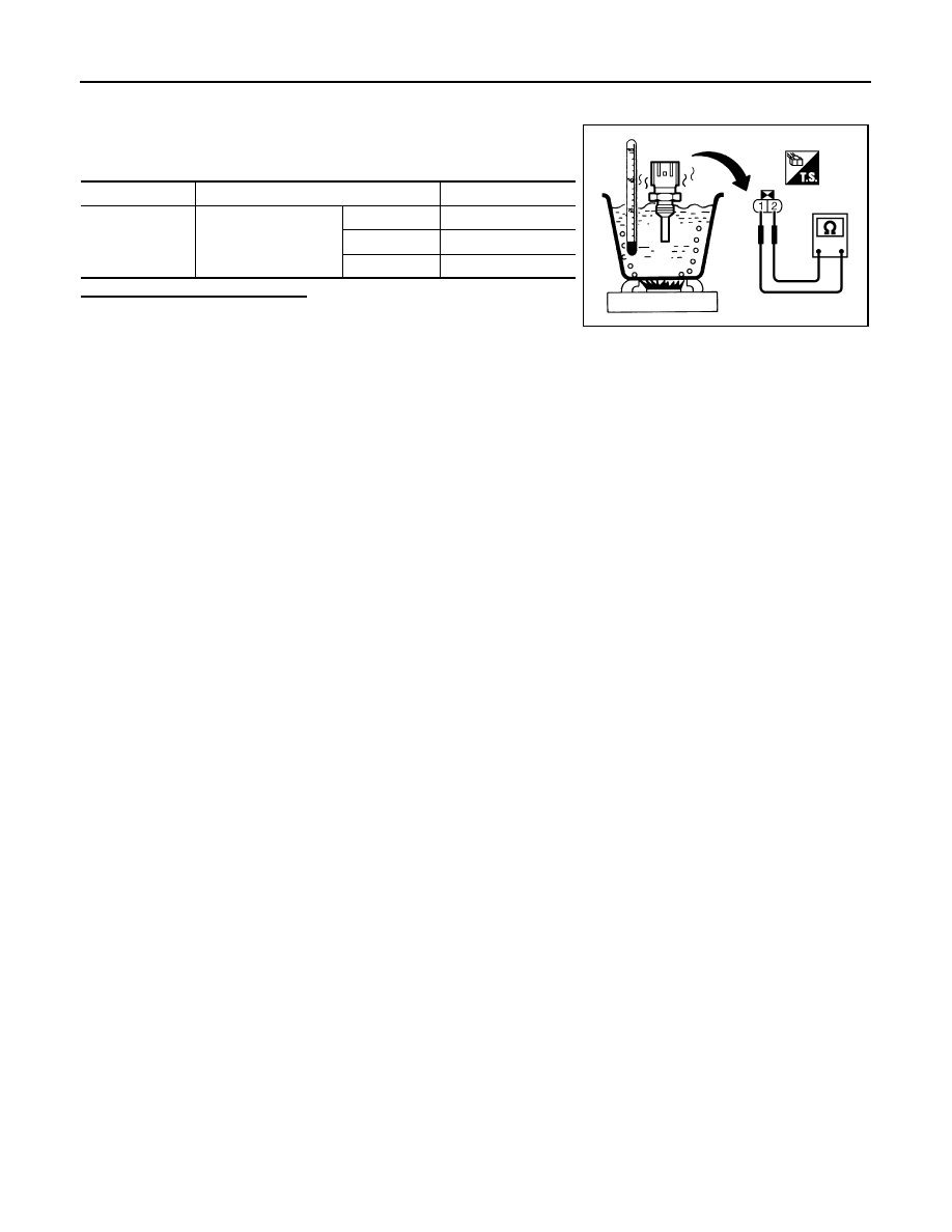
2. Disconnect engine coolant temperature sensor harness connector.

3. Remove engine coolant temperature sensor.

4. Check resistance between engine coolant temperature sensor

terminals by heating with hot water as shown in the figure.

Is the inspection result normal?

YES

>> INSPECTION END

NO

>> Replace engine coolant temperature sensor.

Terminals

Condition

Resistance

1 and 2

Temperature 

°C (°F)

20 (68)

2.37 - 2.63 k

50 (122)

0.68 - 1.00 k

90 (194)

0.236 - 0.260 k

PBIB2005E

P0122, P0123 TP SENSOR

EC-169

< COMPONENT DIAGNOSIS >

[QR25DE]

C

D

E

F

G

H

I

J

K

L

M

A

EC

N

P

O

P0122, P0123 TP SENSOR

Description

INFOID:0000000004211405

Electric throttle control actuator consists of throttle control motor,

throttle position sensor, etc. The throttle position sensor responds to

the throttle valve movement. 

The throttle position sensor has two sensors. These sensors are a

kind of potentiometers which transform the throttle valve position into

output voltage, and emit the voltage signal to the ECM. In addition,

these sensors detect the opening and closing speed of the throttle

valve and feed the voltage signals to the ECM. The ECM judges the

current opening angle of the throttle valve from these signals and the

ECM controls the throttle control motor to make the throttle valve

opening angle properly in response to driving condition.

DTC Logic

INFOID:0000000004211406

DTC DETECTION LOGIC

NOTE:

If DTC P0122 or P0123 is displayed with DTC P0643, first perform the trouble diagnosis for DTC P0643.

Refer to 

EC-321, "DTC Logic"

.

DTC CONFIRMATION PROCEDURE

1.

PRECONDITIONING

If DTC Confirmation Procedure has been previously conducted, always perform the following before conduct-

ing the next test.

1. Turn ignition switch OFF and wait at least 10 seconds.

2. Turn ignition switch ON.

3. Turn ignition switch OFF and wait at least 10 seconds.

TESTING CONDITION:

Before performing the following procedure, confirm that battery voltage is more than 8V at idle.

>> GO TO 2.

2.

PERFORM DTC CONFIRMATION PROCEDURE

1. Turn ignition switch ON (READY).

2. Depress the accelerator pedal to start engine, then keep engine running for at least 1 second.

3. Check DTC.
Is DTC detected?

YES

>> Go to 

EC-169, "Diagnosis Procedure"

.

NO

>> INSPECTION END

Diagnosis Procedure

INFOID:0000000004211407

1.

CHECK GROUND CONNECTION

1. Turn ignition switch OFF.

2. Check ground connection E9. Refer to Ground Inspection in 

GI-45, "Circuit Inspection"

.

Is the inspection result normal?

YES

>> GO TO 2.

NO

>> Repair or replace ground connection.

PBIB0145E

DTC No.

Trouble diagnosis name

DTC detecting condition

Possible cause

P0122

Throttle position sensor 
2 circuit low input

An excessively low voltage from the TP sensor 
2 is sent to ECM.

• Harness or connectors

(TP sensor 2 circuit is open or shorted.)

• Electric throttle control actuator

(TP sensor 2)

P0123

Throttle position sensor 
2 circuit high input

An excessively high voltage from the TP sensor 
2 is sent to ECM.

EC-170

< COMPONENT DIAGNOSIS >

[QR25DE]

P0122, P0123 TP SENSOR

2.

CHECK THROTTLE POSITION SENSOR 2 POWER SUPPLY CIRCUIT

1. Disconnect electric throttle control actuator harness connector.

2. Turn ignition switch ON.

3. Check the voltage between electric throttle control actuator har-

ness connector and ground.

Is the inspection result normal?

YES

>> GO TO 3.

NO

>> Repair open circuit or short to ground or short to power

in harness or connectors.

3.

CHECK THROTTLE POSITION SENSOR 2 GROUND CIRCUIT FOR OPEN AND SHORT

1. Turn ignition switch OFF.

2. Disconnect ECM harness connector.

3. Check the continuity between electric throttle control actuator harness connector and ECM harness con-

nector.

4. Also check harness for short to ground and short to power.
Is the inspection result normal?

YES

>> GO TO 4.

NO

>> Repair open circuit or short to ground or short to power in harness or connectors.

4.

CHECK THROTTLE POSITION SENSOR 2 INPUT SIGNAL CIRCUIT FOR OPEN AND SHORT

1. Check the continuity between electric throttle control actuator harness connector and ECM harness con-

nector.

2. Also check harness for short to ground and short to power.
Is the inspection result normal?

YES

>> GO TO 5.

NO

>> Repair open circuit or short to ground or short to power in harness or connectors.

5.

CHECK THROTTLE POSITION SENSOR

Refer to 

EC-171, "Component Inspection"

.

Is the inspection result normal?

YES

>> GO TO 7.

NO

>> GO TO 6.

6.

REPLACE ELECTRIC THROTTLE CONTROL ACTUATOR

1. Replace electric throttle control actuator.

2. Go to 

EC-171, "Special Repair Requirement"

.

>> INSPECTION END

7.

CHECK INTERMITTENT INCIDENT

Electric throttle control actuator

Ground

Voltage

Connector

Terminal

F57

1

Ground

Approx. 5V

JMBIA1584ZZ

Electric throttle control actuator

ECM

Continuity

Connector

Terminal

Connector

Terminal

F57

4

F13

36

Existed

Electric throttle control actuator

ECM

Continuity

Connector

Terminal

Connector

Terminal

F57

3

F13

38

Existed

P0122, P0123 TP SENSOR

EC-171

< COMPONENT DIAGNOSIS >

[QR25DE]

C

D

E

F

G

H

I

J

K

L

M

A

EC

N

P

O

Refer to 

GI-42, "Intermittent Incident"

.

>> INSPECTION END

Component Inspection

INFOID:0000000004211408

1.

CHECK THROTTLE POSITION SENSOR

1. Turn ignition switch OFF.

2. Reconnect all harness connectors disconnected.

3. Perform 

EC-15, "THROTTLE VALVE CLOSED POSITION LEARNING : Special Repair Requirement"

.

4. Turn ignition switch ON.

5. Set shift lever to D position. 

6. Check the voltage between ECM harness connector and

ground.

Is the inspection result normal?

YES

>> INSPECTION END

NO

>> GO TO 2.

2.

REPLACE ELECTRIC THROTTLE CONTROL ACTUATOR

1. Replace electric throttle control actuator.

2. Go to 

EC-171, "Special Repair Requirement"

.

>> INSPECTION END

Special Repair Requirement

INFOID:0000000004211409

1.

PERFORM THROTTLE VALVE CLOSED POSITION LEARNING

Refer to 

EC-15, "THROTTLE VALVE CLOSED POSITION LEARNING : Special Repair Requirement"

>> GO TO 2.

2.

PERFORM IDLE AIR VOLUME LEARNING

Refer to 

EC-16, "IDLE AIR VOLUME LEARNING : Special Repair Requirement"

>> END

ECM

Ground

Condition

Voltage

Connector

Terminal

F13

37

(TP sensor 

1 signal)

Ground

Accelerator 
pedal

Fully 
released

More than 0.36 V

Fully 
depressed

Less than 4.75 V

38

 (TP sensor 

2 signal)

Fully 
released

Less than 4.75 V

Fully 
depressed

More than 0.36 V

JMBIA1634ZZ


Content   ..  294  295  296  297   ..