Nissan Altima HL32 Hybrid. Manual - part 134


  Index      Nissan     Nissan Altima HL32 Hybrid (2009 year) - Service and Repair Manual


Search            


Content   ..  132  133  134  135   ..


Nissan Altima HL32 Hybrid. Manual - part 134


C1252, C1253

BRC-101

< COMPONENT DIAGNOSIS >

[VDC/TCS/ABS]

C

D

E

G

H

I

J

K

L

M

A

B

BRC

N

O

P

2. Measure the resistance according to the value(s) in the table

below.

Is the inspection result normal?

YES

>> GO TO 5.

NO

>> Repair or replace harness or connector.

5.

READ VALUE OF CONSULT-III (ACCUMULATOR PRESSURE SENSOR)

1. Reconnect the brake ECU connector and the brake actuator connector.

2. Connect the CONSULT-III.

3. Turn the ignition switch ON.

4. Select the “DATA MONITOR” on the CONSULT-III.

ABS/VDC:

5. Depress the brake pedal 4 or 5 times to operate the pump motor, and check the output value on the CON-

SULT-III with the motor stopped (not braking).

NOTE:

Accumulator pressure sensor voltage does not drop.

Is the inspection result normal?

YES

>> GO TO 6.

NO

>> Replace brake actuator assembly.

6.

RECONFIRM DTC

1. Turn the ignition switch OFF.

2. Clear the DTC.

3. Turn the ignition switch ON.

4. Check if the same DTC is recorded.

Result

A

>> Check for intermittent problems (symptom simulation).

B

>> Replace brake ECU.

7.

INSPECT ABS MOTOR RELAY (ABS MOTOR RELAY NO.1 AND NO.2)
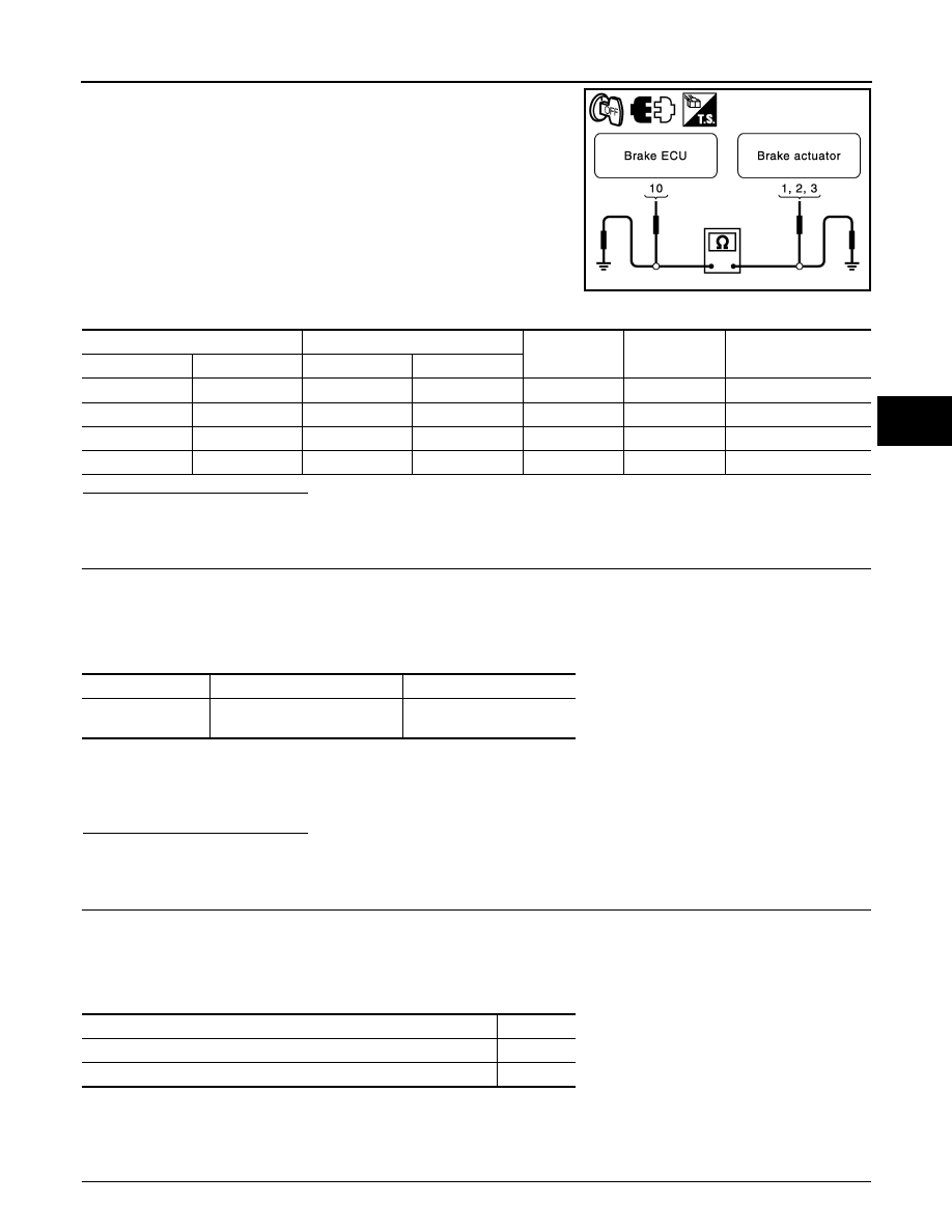
JSFIA0353GB

Brake ECU

Brake actuator

Condition

Specified condition

Connector

Terminal

Connector

Terminal

E60

10

E91

3

Always

Below 1 

E60

10

Ground

Always

10 k

Ω or higher

E91

1

Ground

Always

Below 1 

E91

2

Ground

Always

Below 1 

Tester display

Measurement item/ Range

Normal condition

ACC PRESS SEN

Accumulator pressure sensor/ 
min: 0 V, max: 5 V

Around: 3.3 to 4.7 V

Condition

Proceed to

DTCs (C1252 and/or C1253) are not output.

A

DTCs (C1252 and/or C1253) are output.

B

B R C - 1 0 2

< COMPONENT DIAGNOSIS >

[VDC/TCS/ABS]

C1252, C1253

1. Turn the ignition switch OFF.

2. Remove the ABS motor relay No.1 and the ABS motor relay No.2.

3. Measure the resistance according to the value(s) in the table

below.

Is the inspection result normal?

YES

>> GO TO 8.

NO

>> Replace ABS motor relay (ABS motor relay No.1 or

No.2).

8.

INSPECT ENGINE ROOM NO.3 RELAY BLOCK (POWER SOURCE TERMINAL)

Measure the voltage according to the value(s) in the table below.

Is the inspection result normal?

YES

>> GO TO 9.

NO

>> Repair or replace harness or connector (power source

circuit).

9.

CHECK HARNESS AND CONNECTOR (BRAKE ACTUATOR – ENGINE ROOM NO.3 RELAY BLOCK)

1. Disconnect the brake actuator connector.

2. Measure the resistance according to the value(s) in the table

below.

Is the inspection result normal?

YES

>> GO TO 10.

NO

>> Repair or replace harness or connector.

Terminal

Condition

Specified condition

3 – 5

Always

10 k

Ω or higher

3 – 5

Apply B+ between termi-

nals 1 and 2

Below 1 

JSFIA0354GB

Relay

Terminal

Condition

Specified condition

ABS motor relay No.1

3

Always

10 to 14 V

ABS motor relay No.2

3

Always

10 to 14 V

JSFIA0355GB

JSFIA0356GB

Brake actuator

ABS motor relay 1

Condition

Specified condition

Connector

Terminal

Connector

Terminal

E91

31

E87

5

Always

Below 1 

E91

31

Ground

Always

10 k

Ω or higher

Brake actuator

ABS motor relay 2

Condition

Specified condition

Connector

Terminal

Connector

Terminal

E91

32

E86

5

Always

Below 1 

E91

32

Ground

Always

10 k

Ω or higher

C1252, C1253

BRC-103

< COMPONENT DIAGNOSIS >

[VDC/TCS/ABS]

C

D

E

G

H

I

J

K

L

M

A

B

BRC

N

O

P

10.

CHECK HARNESS OR CONNECTOR (BRAKE ECU – ENGINE ROOM NO.3 RELAY BLOCK)

1. Disconnect the brake ECU connectors.

2. Measure the resistance according to the value(s) in the table

below.

Is the inspection result normal?

YES

>> GO TO 11.

NO

>> Repair or replace harness or connector.

11.

RECONFIRM DTC

1. Clear the DTC.

2. Turn the ignition switch ON.

3. Check if the same DTC is recorded.

NOTE:

Reinstall the relays, connectors, etc. and restore the vehicle to its prior condition before rechecking for

DTCs.

Result

A

>> Check for intermittent problems (symptom simulation).

B

>> Replace brake ECU.

Special Repair Requirement

INFOID:0000000004212682

1.

ZERO ADJUSTMENT FOR EACH SENSOR AND OFFSET LEANING FOR LINEAR SOLENOID VALVE

After erasing brake ECU memories, perform zero adjustment of following sensors and initialization of linear

solenoid valve.

JSFIA0357GB

Brake ECU

ABS motor relay 1

Condition

Specified condition

Connector

Terminal

Connector

Terminal

E60

11

E87

2

Always

Below  1 

E60

11

Ground

Always

10 k

Ω or higher

E60

25

E87

1

Always

Below 1 

E60

25

Ground

Always

10 k

Ω or higher

Brake ECU

ABS motor relay 2

Condition

Specified condition

Connector

Terminal

Connector

Terminal

E61

71

E86

2

Always

Below 1 

E61

71

Ground

Always

10 k

Ω or higher

E61

59

E86

1

Always

Below 1 

E61

59

Ground

Always

10 k

Ω or higher

Condition

Proceed to

DTCs (C1252 and/or C1253) are not output.

A

DTCs (C1252 and/or C1253) are output.

B


Content   ..  132  133  134  135   ..