Nissan Altima HL32 Hybrid. Manual - part 135


  Index      Nissan     Nissan Altima HL32 Hybrid (2009 year) - Service and Repair Manual


Search            


Content   ..  133  134  135  136   ..


Nissan Altima HL32 Hybrid. Manual - part 135


C1256

BRC-105

< COMPONENT DIAGNOSIS >

[VDC/TCS/ABS]

C

D

E

G

H

I

J

K

L

M

A

B

BRC

N

O

P

C1256

Description

INFOID:0000000004212683

The accumulator pressure snesor is built into the actuator and detects the accumulator pressure.

The brake ECU turns on the brake warning lamp and sounds the brake warning buzzer if it senses a decrease

in the accumulator pressure.

DTC Logic

INFOID:0000000004212684

Diagnosis Procedure

INFOID:0000000004212685

CAUTION:

When replacing the brake ECU or brake actuator assembly, perform initialization of linear solenoid

valve and calibration.

NOTE:

When C1241, C1252 or C1253 is output together with C1256, inspect and repair the trouble areas indicated

by C1241, C1252 or C1253 first.

1.

BRAKE PROBLEM CHECK

Ask the customer if frequent braking is performed when the brake control warning lamp comes on.

NOTE:

This DTC is output even if the accumulator pressure drops only temporarily due to frequent braking.

A

>> GO TO 2.

B

>> INSPECTION END

2.

READ VALUE OF CONSULT-III (ACCUMULATOR PRESSURE SENSOR)

1. Connect the CONSULT-III.

2. Turn the ignition switch ON.
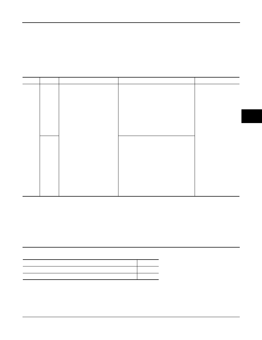
DTC

INF code

Display item

DTC detection condition

Trouble area

C1256

141

ACC PRESSURE LOW

When either of the following is detected:
1.

Braking operation is input when accumu-
lator pressure is less than 12.45 Mpa 
and vehicle speed is input (detected val-
ue changes if accumulator pressure is 
low after system start).

2.

Accumulator pressure is less than 14.62 
Mpa for 120 seconds (changes accord-
ing to power source voltage) after sys-
tem start (stores the DTC after the 
conditions are met, and drives buzzer).

• Accumulator pressure
• Brake actuator assem-

bly (Accumulator pres-
sure sensor)

• Brake actuator assem-

bly (Pump motor)

143

When any of the following is detected:
1.

Any of the wheel cylinder pressure sen-
sor value is lower than the target value 
for at least 0.5 seconds when accumula-
tor pressure is less than 14.62 Mpa and 
vehicle speed is input.

2.

Accumulator pressure changes little 
when accumulator pressure is less than 
14.62 Mpa for at least 1 second without 
braking (pump motor is operating).

3.

Accumulator pressure is less than 14.62 
Mpa for at least 0.5 seconds when motor 
relay is malfunctioning.

Condition

Proceed to

Frequent braking is performed.

A

Frequent braking is not performed.

B

BRC-106

< COMPONENT DIAGNOSIS >

[VDC/TCS/ABS]

C1256

3. Select the “DATA MONITOR” on the CONSULT-III.

ABS/VDC:

4. Depress the brake pedal 4 or 5 times to operate the pump motor, and check the output value on the CON-

SULT-III with the motor stopped (not braking).

NOTE:

Accumulator pressure sensor

′s output voltage does not drop.

Is the inspection result normal?

YES

>> GO TO 3.

NO

>> GO TO 4.

3.

INSPECT BRAKE ACTUATOR ASSEMBLY

1. Turn the ignition switch OFF.

2. Disconnect the brake actuator connector.

3. Measure the resistance according to the value(s) in the table

below.

Is the inspection result normal?

YES

>> GO TO 4.

NO

>> Replace brake actuator assembly.

4.

RECONFIRM DTC

1. Reconnect the brake actuator connector.

2. Clear the DTC.

3. Perform the road and braking test.

4. Check if the same DTC is recorded.

Result

A

>> Check for intermittent problems (symptom simulation).

B

>> Replace brake ECU.

Special Repair Requirement

INFOID:0000000004212686

1.

ZERO ADJUSTMENT FOR EACH SENSOR AND OFFSET LEANING FOR LINEAR SOLENOID VALVE

After erasing brake ECU memories, perform zero adjustment of following sensors and initialization of linear

solenoid valve.

• Steering angle sensor: 

BRC-9, "PERFORM ZERO POINT OF STEERING ANGLE SENSOR : Description"

.

• Yaw rate/side/decel G sensor: 

BRC-8, "PERFORM ZERO POINT OF YAW RATE/SIDE/DECEL G SENSOR

: Description"

.

• Brake stroke sensor: 

BRC-9, "PERFORM ADJUSTMENT OF STROKE SENSOR : Description"

.

Tester display

Measurement item/ Range

Normal condition

ACC PRESS SEN

Accumulator pressure sensor/ 
min: 0 V, max: 5 V

Around: 3.3 to 4.7 V

Brake actuator

Condition

Specified condition

Connector

Terminal

E91

32 – 2

Always

Below 10 

E91

31 – 2

Always

Below 10 

E91

31 – 32

Always

Below 1 

E91

1 – 2

Always

Below 1 

E91

32 – 3

Always

450 to 550 

E91

31 – 3

Always

450 to 550 

JSFIA0352GB

Condition

Proceed to

DTCs (C1252 and/or C1253) are not output.

A

DTCs (C1252 and/or C1253) are output.

B

C1256

BRC-107

< COMPONENT DIAGNOSIS >

[VDC/TCS/ABS]

C

D

E

G

H

I

J

K

L

M

A

B

BRC

N

O

P

• Linear solenoid valve: 

BRC-7, "PERFORM INITIALIZATION OF LINEAR SOLENOID VALVE AND CALI-

BRATION : Description"

.

>> END

BRC-108

< COMPONENT DIAGNOSIS >

[VDC/TCS/ABS]

C1259, C1310

C1259, C1310

Description

INFOID:0000000004212687

The brake ECU communicates with the HV ECU and controls braking force according to the motor

′s regener-

ative force.

The brake ECU sends enhanced VDC signal to the HV ECU and inputs operating signal from the HV control

ECU.

The brake ECU uses CAN communication for communication with the HV ECU. If a part of Electronically Con-

trolled Brake control by fail safe function.

C1259 is stored if the ignition switch ON with the HV battery service plug disconnected.

DTC Logic

INFOID:0000000004212688

NOTE:

This DTC is output from the brake ECU when the HV ECU sends a malfunction signal to the brake ECU.

Diagnosis Procedure

INFOID:0000000004212689

1.

CHECK HYBRID CONTROL SYSTEM

Check if the hybrid control system DTC is output.

DTC is not output>>Replace HV ECU.

DTC is output>>Inspect hybrid control system.

Special Repair Requirement

INFOID:0000000004212690

1.

ZERO ADJUSTMENT FOR EACH SENSOR AND OFFSET LEANING FOR LINEAR SOLENOID VALVE

After erasing brake ECU memories, perform zero adjustment of following sensors and initialization of linear

solenoid valve.

• Steering angle sensor: 

BRC-9, "PERFORM ZERO POINT OF STEERING ANGLE SENSOR : Description"

.

• Yaw rate/side/decel G sensor: 

BRC-8, "PERFORM ZERO POINT OF YAW RATE/SIDE/DECEL G SENSOR

: Description"

.

• Brake stroke sensor: 

BRC-9, "PERFORM ADJUSTMENT OF STROKE SENSOR : Description"

.

• Linear solenoid valve: 

BRC-7, "PERFORM INITIALIZATION OF LINEAR SOLENOID VALVE AND CALI-

BRATION : Description"

.

>> END

DTC

INF code

Display item

DTC detection condition

Trouble area

C1259

150

HV SYSTEM REGNRTNG

The regeneration malfunction signal is input 
for at least 0.02 seconds when IG1 terminal 
voltage is 9.5 V or more for at least 2 seconds 
and communication with HV ECU is valid.

• Hybrid control system

C1310

HV SYSTEM

The traction control prohibition signal is re-
ceived for at least 0.07 seconds when IG1 ter-
minal voltage is 10.5 V or more for at least 1.5 
seconds and communication with HV ECU is 
valid.


Content   ..  133  134  135  136   ..