Nissan Altima HL32 Hybrid. Manual - part 131
C1246, C1281, C1364
BRC-89
< COMPONENT DIAGNOSIS >
[VDC/TCS/ABS]
C
D
E
G
H
I
J
K
L
M
A
B
BRC
N
O
P
Is the inspection result normal?
YES
>> GO TO 2.
NO
>> Repair or replace harness or connector.
2.
READ VALUE OF CONSULT-III (MASTER CYLINDER PRESSURE SENSOR)
1. Reconnect the brake actuator connector.
2. Connect the pedal effort gauge.
3. Connect the CONSULT-III.
4. Turn the ignition switch ON.
5. Select the “DATA MONITOR” on the CONSULT-III.
ABS/VDC
6. Check the output value of the master cylinder pressure snesor at braking.
NOTE:
Output voltage must be proportional to the degree of pedal depression. There should not be a big differ-
ence between outputs of sensor 1 and sensor 2.
Is the inspection result normal?
YES
>> GO TO 3.
NO
>> Replace brake actuator assembly.
3.
READ VALUE OF CONSULT-III (WHEEL CYLINDER PRESSURE SENSOR)
1. Turn the ignition switch OFF.
2. Turn the ignition switch ON.
3. Select the “DATA MONITOR” on the CONSULT-III.
ABS/VDC
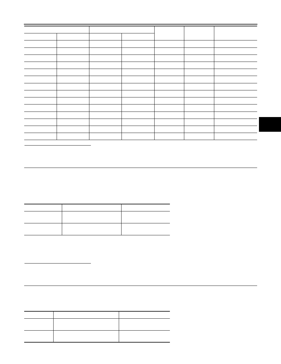
E60
36
E91
12
—
Always
Below 1
Ω
E60
36
—
—
Ground
Always
10 k
Ω or higher
E61
65
E91
5
—
Always
Below 1
Ω
E61
65
—
—
Ground
Always
10 k
Ω or higher
E61
83
E91
7
—
Always
Below 1
Ω
E61
83
—
—
Ground
Always
10 k
Ω or higher
E61
52
E91
4
—
Always
Below 1
Ω
E61
52
—
—
Ground
Always
10 k
Ω or higher
E61
77
E91
8
—
Always
Below 1
Ω
E61
77
—
—
Ground
Always
10 k
Ω or higher
E61
53
E91
16
—
Always
Below 1
Ω
E61
53
—
—
Ground
Always
10 k
Ω or higher
E61
54
E91
6
—
Always
Below 1
Ω
E61
54
—
—
Ground
Always
10 k
Ω or higher
Brake ECU
Brake actuator
—
Condition
Specified condition
Connector
Terminal
Connector
Terminal
Tester display
Measurement item/ Range
Normal condition
MC SEN COMP 1
Master cylinder pressure snesor
1 reading/ min: 0 V, max: 5 V
When brake pedal is re-
leased: 0.3 to 0.9 V
MC SEN COMP 2
Master cylinder pressure snesor
2 reading/ min: 0 V, max: 5 V
When brake pedal is re-
leased: 0.3 to 0.9 V
Tester display
Measurement item/ Range
Normal condition
FR WC
PRESS
FR wheel cylinder pressure sensor/
min: 0 V, max: 5 V
When brake pedal is re-
leased: 0.3 to 0.9 V
FL WC
PRESS
FL wheel cylinder pressure sensor/
min: 0 V, max: 5 V
When brake pedal is re-
leased: 0.3 to 0.9 V