Nissan Altima HL32 Hybrid. Manual - part 130
 

  Index      Nissan     Nissan Altima HL32 Hybrid (2009 year) - Service and Repair Manual


Search            


Content   ..  128  129  130  131   ..


Nissan Altima HL32 Hybrid. Manual - part 130


C1241, C1242

BRC-85

< COMPONENT DIAGNOSIS >

[VDC/TCS/ABS]

C

D

E

G

H

I

J

K

L

M

A

B

BRC

N

O

P

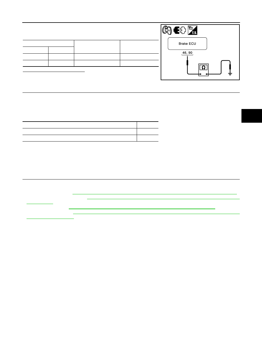
2. Measure the resistance according to the value(s) in the table

below.

Is the inspection result normal?

YES

>> GO TO 5.

NO

>> Repair or replace harness or connector (GND circuit).

5.

RECONFIRM DTC

1. Turn the ignition switch OFF.

2. Clear the DTC.

3. Turn the ignition switch ON.

4. Check if the same DTC is recorded.

Result

A

>> Check for intermittent problems (symptom simulation).

B

>> Replace brake ECU.

Special Repair Requirement

INFOID:0000000004212666

1.

ZERO ADJUSTMENT FOR EACH SENSOR AND OFFSET LEANING FOR LINEAR SOLENOID VALVE

After erasing brake ECU memories, perform zero adjustment of following sensors and initialization of linear

solenoid valve.

• Steering angle sensor: 

BRC-9, "PERFORM ZERO POINT OF STEERING ANGLE SENSOR : Description"

.

• Yaw rate/side/decel G sensor: 

BRC-8, "PERFORM ZERO POINT OF YAW RATE/SIDE/DECEL G SENSOR

: Description"

.

• Brake stroke sensor

BRC-9, "PERFORM ADJUSTMENT OF STROKE SENSOR : Description"

.

• Linear solenoid valve: 

BRC-7, "PERFORM INITIALIZATION OF LINEAR SOLENOID VALVE AND CALI-

BRATION : Description"

.

>> END

Brake ECU

Condition

Specified condition

Connector

Terminal

E60

46 – Ground

Always

Below 1 

E61

90 – Ground

Always

Below 1 

JSFIA0343GB

Condition

Proceed to

DTCs (C1241 and/or C1242) are not output.

A

DTCs (C1241 and/or C1242) are output.

B

BRC-86

< COMPONENT DIAGNOSIS >

[VDC/TCS/ABS]

C1246, C1281, C1364

C1246, C1281, C1364

Description

INFOID:0000000004212667

The master cylinder pressure sensor and the wheel cylinder pressure sensor are built into the brake actuator,

and measure the master cylinder pressure and the wheel cylinder pressure sent to the brake ECU.

DTC C1281 can be deleted when the master cylinder pressure sensor sends a master cylinder pressure sig-

nal or the Test Mode ends. DTC C1281 is output only in the Test Mode.

DTC Logic

INFOID:0000000004212668

DTC

INF code

Display item

DTC detection condition

Trouble area

C1246

191

MC PRESS SENSOR

Sensor power source 1 (VCM1) voltage is less 
than 4.7 V or 5.3 V or more for at least 0.05 
seconds.

• Brake actuator assem-

bly (Master cylinder 
pressure sensor)

• Master cylinder pres-

sure sensor circuit

• Master cylinder pres-

sure sensor power sup-
ply

• Brake actuator assem-

bly

• Brake  ECU

194

Sensor power source 2 (VCM2) voltage is less 
than 4.7 V or 5.3 V or more for at least 0.05 
seconds.

192

Ratio of M/C pressure sensor output voltage 1 
(PMC1) to sensor power source 1 (VCM1) is 
less than 5% or 90.5% or more for at least 
0.05 seconds.

• Brake actuator assem-

bly (Master cylinder 
pressure sensor)

• Master cylinder pres-

sure sensor circuit

• Brake actuator assem-

bly

• Brake  ECU

195

Ratio of M/C pressure sensor output voltage 2 
(PMC2) to sensor power source 2 (VCM2) is 
less than 5% or 90.5% or more for at least 
0.05 seconds.

197

M/C pressure sensor output voltage 1 (PMC1) 
is abnormal.

• Brake actuator assem-

bly

• Brake  ECU

198

M/C pressure sensor output voltage 2 (PMC2) 
is abnormal.

199

M/C pressure sensor output 1 (PMC1) is not 
approx. 0 Mpa when not braking.

• Brake actuator assem-

bly (Master cylinder 
pressure sensor)

• Master cylinder pres-

sure sensor circuit

• Brake actuator assem-

bly

• Brake  ECU

200

M/C pressure sensor output 2 (PMC2) is not 
approx. 0 Mpa when not braking.

201

PMC1 and PMC2 voltages are different when 
braking.

202

M/C pressure sensor 1 data (PMC1) is invalid. • Master cylinder pres-

sure sensor power sup-
ply

• Brake actuator assem-

bly

• Brake  ECU

205

M/C pressure sensor 2 data (PMC2) is invalid.

C1246, C1281, C1364

BRC-87

< COMPONENT DIAGNOSIS >

[VDC/TCS/ABS]

C

D

E

G

H

I

J

K

L

M

A

B

BRC

N

O

P

C1364

221

WC PRESS SEN

Sensor power source 1 (VCM1) voltage is less 
than 4.7 V or 5.3 V or more for at least 0.05 
seconds.

• Wheel cylinder pres-

sure sensor power sup-
ply

• Brake actuator assem-

bly

• Brake  ECU

227

Sensor power source 2 (VCM2) voltage is less 
than 4.7 V or 5.3 V or more for at least 0.05 
seconds.

222

• Ratio of FR right sensor output voltage 

(PFR) to sensor power source 1 (VCM1) is 
less than 5% or 90.5% or more for at least 
0.05 seconds.

• Open or short in FR right sensor (PFR) cir-

cuit.

• Brake actuator assem-

bly (wheel cylinder 
pressure sensor)

• Wheel cylinder pres-

sure sensor

• Brake actuator assem-

bly

• Brake  ECU

224

When any of the following is detected:
1.

FR right sensor output (PFR) is not ap-
prox. 0 Mpa when not braking.

2.

FR right sensor (PFR) zero point mal-
function.

225

Ratio of FR right sensor output voltage (PFR) 
to sensor power source 1 (VCM1) is less than 
90.5% for at least 0.1 second when self diag-
nosis signal is output.

228

• Ratio of FR left sensor output voltage (PFL) 

to sensor power source 2 (VCM2) is less 
than 5% or 90.5% or more for at least 0.05 
seconds.

• Open or short in FR left sensor (PFL) circuit.

• Brake actuator assem-

bly (wheel cylinder 
pressure sensor)

• Wheel cylinder pres-

sure sensor

• Brake actuator assem-

bly

• Brake  ECU

230

When any of the following is detected:
1.

FR left sensor output (PFL) is not ap-
prox. 0 Mpa when not braking.

2.

FR left sensor (PFL) zero point malfunc-
tion.

231

Ratio of FR left sensor output voltage (PFL) to 
sensor power source 2 (VCM2) is less than 
90.5% for at least 0.1 second when self diag-
nosis signal is output.

233

Sensor power source 2 (VCM2) voltage is less 
than 4.7 V or 5.3 V or more for at least 0.05 
seconds.

• Wheel cylinder pres-

sure sensor power sup-
ply

• Brake actuator assem-

bly

• Brake  ECU

239

Sensor power source 1 (VCM1) voltage is less 
than 4.7 V or 5.3 V or more for at least 0.05 
seconds.

234

• Ratio of RR right sensor output voltage 

(PRR) to sensor power source 2 (VCM2) is 
less than 5% or 90.5% or more for at least 
0.05 seconds.

• Open or short in RR right sensor (PRR) sir-

cuit.

• Brake actuator assem-

bly (wheel cylinder 
pressure sensor)

• Wheel cylinder pres-

sure sensor circuit

• Brake actuator assem-

bly

• Brake  ECU

236

When any of the following is detected:
1.

RR right sensor output (PRR) is not ap-
prox. 0 Mpa when not braking.

2.

RR right sensor (PRR) zero point mal-
function.

237

Ratio of RR right sensor output voltage (PRR) 
to sensor power source 2 (VCM2) is less than 
90.5% for at least 0.1 second when self diag-
nosis signal is output.

DTC

INF code

Display item

DTC detection condition

Trouble area

BRC-88

< COMPONENT DIAGNOSIS >

[VDC/TCS/ABS]

C1246, C1281, C1364

Diagnosis Procedure

INFOID:0000000004212669

CAUTION:

When replacing the brake ECU or brake actuator assembly, perform initialization of linear solenoid

valve and calibration.

1.

CHECK HARNESS AND CONNECTOR (BRAKE ECU – BRAKE ACTUATOR)

1. Disconnect the brake ECU connectors and the brake actuator connector.

2. Measure the resistance according to the value(s) in the table

below.

C1364

240

WC PRESS SEN

• Ratio of RR left sensor output voltage (PRL) 

to sensor power source 1 (VCM1) is less 
than 5% or 90.5% or more for at least 0.05 
seconds.

• Open or short in RR left sensor (PRL) sir-

cuit.

• Brake actuator assem-

bly (wheel cylinder 
pressure sensor)

• Wheel cylinder pres-

sure sensor circuit

• Brake actuator assem-

bly

• Skid control ECU

242

When any of the following is detected:
1.

RR left sensor output (PRL) is not ap-
prox. 0 Mpa when not braking.

2.

RR left sensor (PRL) zero point malfunc-
tion.

243

Ratio of RR left sensor output voltage (PRL) to 
sensor power source 1 (VCM1) is less than 
90.5% for at least 0.1 second when self diag-
nosis signal is output.

C1281

MC SENSOR OUTPUT

Detected only during Test Mode.

• Stop lamp switch
• Master cylinder pres-

sure sensor

DTC

INF code

Display item

DTC detection condition

Trouble area

JSFIA0344GB

Brake ECU

Brake actuator

Condition

Specified condition

Connector

Terminal

Connector

Terminal

E60

4

E91

14

Always

Below 1 

E60

4

Ground

Always

10 k

Ω or higher

E60

18

E91

10

Always

Below 1 

E60

18

Ground

Always

10 k

Ω or higher

E60

19

E91

15

Always

Below 1 

E60

19

Ground

Always

10 k

Ω or higher

E60

3

E91

9

Always

Below  1 

E60

3

Ground

Always

10 k

Ω or higher

E60

5

E91

11

Always

Below 1 

E60

5

Ground

Always

10 k

Ω or higher

E60

31

E91

13

Always

Below 1 

E60

31

Ground

Always

10 k

Ω or higher


Content   ..  128  129  130  131   ..