Nissan Altima HL32 Hybrid. Manual - part 1124


  Index      Nissan     Nissan Altima HL32 Hybrid (2009 year) - Service and Repair Manual


Search            


Content   ..  1122  1123  1124  1125   ..


Nissan Altima HL32 Hybrid. Manual - part 1124


TIRE PRESSURE RECEIVER

WT-61

< ON-VEHICLE REPAIR >

C

D

F

G

H

I

J

K

L

M

A

B

WT

N

O

P

ON-VEHICLE REPAIR

TIRE PRESSURE RECEIVER

Removal and Installation

INFOID:0000000004212532
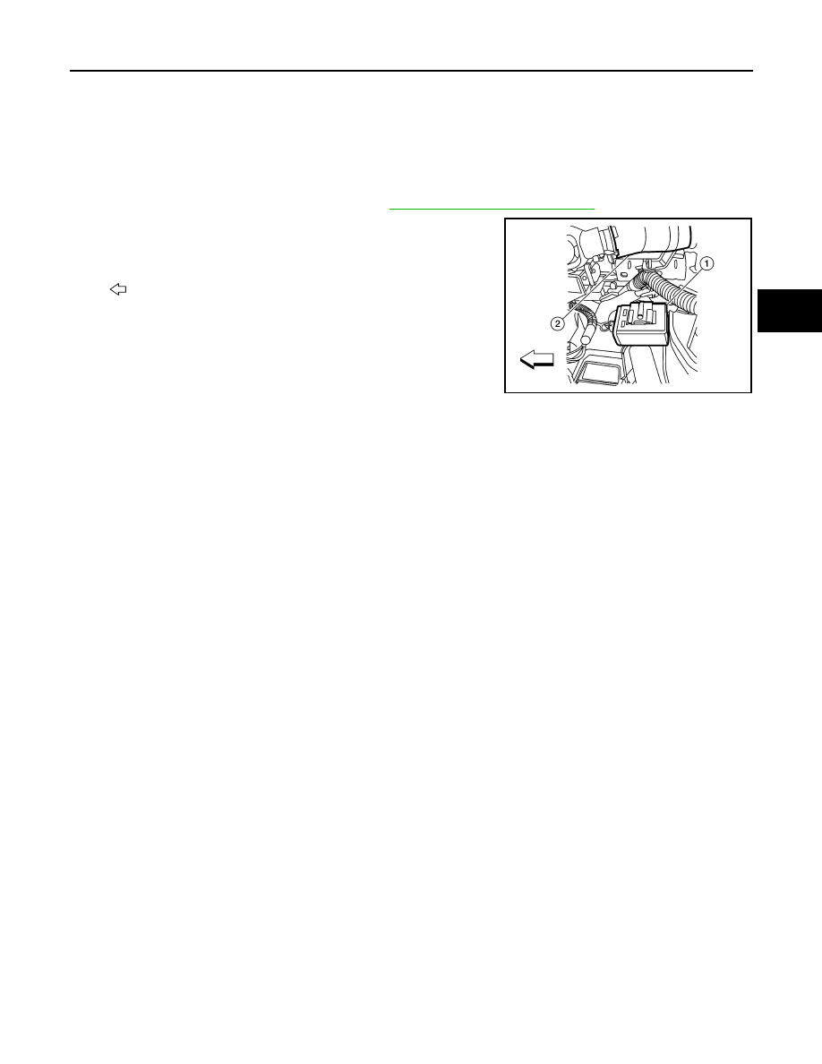
REMOVAL

1. Remove instrument lower cover (LH). Refer to 

IP-12, "Removal and Installation"

.

2. Locate tire pressure receiver (1) to the right of the steering col-

umn (2) and disconnect the tire pressure receiver connector.

3. Remove the tire pressure receiver (1) from bracket using a suit-

able tool to release the bracket.

: Vehicle front

INSTALLATION

Installation is in the reverse order of removal.

ALEIA0011ZZ

WT-62

< ON-VEHICLE REPAIR >

ROAD WHEEL TIRE ASSEMBLY

ROAD WHEEL TIRE ASSEMBLY

Adjustment

INFOID:0000000004212533

WHEEL BALANCE

1. Remove inner and outer balance weights from the wheel.

CAUTION:

• Be careful not to scratch the wheel during removal procedures.

2. Using releasing agent, remove double-faced adhesive tape from the wheel.

CAUTION:

• Be careful not to scratch the wheel during removal.

• After removing double-faced adhesive tape, wipe clean traces of releasing agent from the wheel.

3. Set wheel on wheel balancer using the center hole as a guide. Start the tire balance machine.

• If a tire balance machine has adhesion balance weight mode settings and drive-in weight mode setting,

select and adjust a drive-in weight mode suitable for wheels.

4. When inner and outer unbalance values are shown on the wheel

balancer indicator, multiply outer unbalance value by 1.6 to

determine balance weight that should be used. Select the outer

balance weight with a value closest to the calculated value and

install it to the designated outer position of, or at the designated

angle in relation to the road wheel.

CAUTION:

• Do not install the inner balance weight before installing

the outer balance weight.

• Before installing the balance weight, be sure to clean the

mating surface of the wheel.

Indicated unbalance value 

× 5/3 = balance weight to be installed

Calculation example:

23 g (0.81 oz.) 

× 5/3 = 38.33 g (1.35 oz.) = 40 g (1.41 oz.) balance weight (closer to calculated balance

weight value)

Note that balance weight value must be closer to the calculated balance weight value.

Example:

37.4 g = 35 g (1.23 oz.)

37.5 g = 40 g (1.41 oz.)

a. Install balance weight in the position shown.
b. When installing balance weight to wheels, set it into the grooved

area on the inner wall of the wheel as shown so that the balance

weight center is aligned with the wheel balancer indication posi-

tion (angle).

CAUTION:

• Always use genuine NISSAN adhesion balance weights.

• Balance weights are not reusable; always replace with

new ones.

• Do not install more than three sheets of balance weight.

SMA054D

SMA055D

ROAD WHEEL TIRE ASSEMBLY

WT-63

< ON-VEHICLE REPAIR >

C

D

F

G

H

I

J

K

L

M

A

B

WT

N

O

P

c. If calculated balance weight value exceeds 50 g (1.76 oz.),

install two balance weight sheets in line with each other as

shown.

CAUTION:

Do not install one balance weight sheet on top of another.

5. Start wheel balancer again.
6. Install drive-in balance weight on inner side of road wheel in the

wheel balancer indication position (angle).

CAUTION:

Do not install more than two balance weights.

7. Start wheel balancer. Make sure that inner and outer residual

unbalance values are 5 g (0.18 oz.) each or below.

• If either residual unbalance value exceeds 5 g (0.18 oz.), repeat installation procedures.

Wheel balance (Maximum allowable unbalance):

TIRE ROTATION

• Follow the maintenance schedule for tire rotation service intervals. Refer to 

MA-4, "Explanation General

Maintenance"

.

• Do not include the T-type spare tire when rotating the tires.

CAUTION:

• When installing wheels, tighten them diagonally by dividing

the work two to three times in order to prevent the wheels

from developing any distortion.

• Be careful not to tighten wheel nut at torque exceeding the

criteria for preventing strain of disc rotor.

Maximum allowable un-
balance

Dynamic (At rim flange)

5 g (0.18 oz.) (one side)

Static

10 g (0.35 oz.)

SMA056D

Tightening torque of 
wheel nut

: 113 N·m (12 kg-m, 83 ft-lb)

SMA829C

WT-64

< REMOVAL AND INSTALLATION >

TRANSMITTER

REMOVAL AND INSTALLATION

TRANSMITTER

Removal and Installation

INFOID:0000000004212534

REMOVAL

1. Remove wheel and tire using power tool.
2. Deflate tire. Unscrew transmitter retaining nut and allow transmitter to fall into tire.
3. Gently bounce tire so that transmitter falls to bottom of tire.

Place wheel and tire assembly on tire changing machine and

break both tire beads. Ensure that the transmitter remains at the

bottom of the tire while breaking the bead.

4. Turn tire so that valve hole is at bottom, and gently bounce the

tire to ensure transmitter is near valve hole. Carefully lift tire onto

turntable and position valve hole (and transmitter) 270 degrees

from mounting/dismounting head.

5. Lubricate tire well, and remove top side of tire. Reach inside the

tire and remove the transmitter.

6. Remove the second side of the tire as normal.

INSTALLATION

1. Place first side of tire onto rim.

2. Apply suitable silicone lubricant to new transmitter seal then install seal on transmitter. Refer to 

MA-10,

"Fluids and Lubricants"

.

NOTE:

Always replace the seal after every disassembly.

SEIA0047E

WEIA0046E

SEIA0049E


Content   ..  1122  1123  1124  1125   ..