Nissan Altima HL32 Hybrid. Manual - part 1123


  Index      Nissan     Nissan Altima HL32 Hybrid (2009 year) - Service and Repair Manual


Search            


Content   ..  1121  1122  1123  1124   ..


Nissan Altima HL32 Hybrid. Manual - part 1123


NOISE, VIBRATION AND HARSHNESS (NVH) TROUBLESHOOTING

WT-57

< SYMPTOM DIAGNOSIS >

C

D

F

G

H

I

J

K

L

M

A

B

WT

N

O

P

NOISE, VIBRATION AND HARSHNESS (NVH) TROUBLESHOOTING

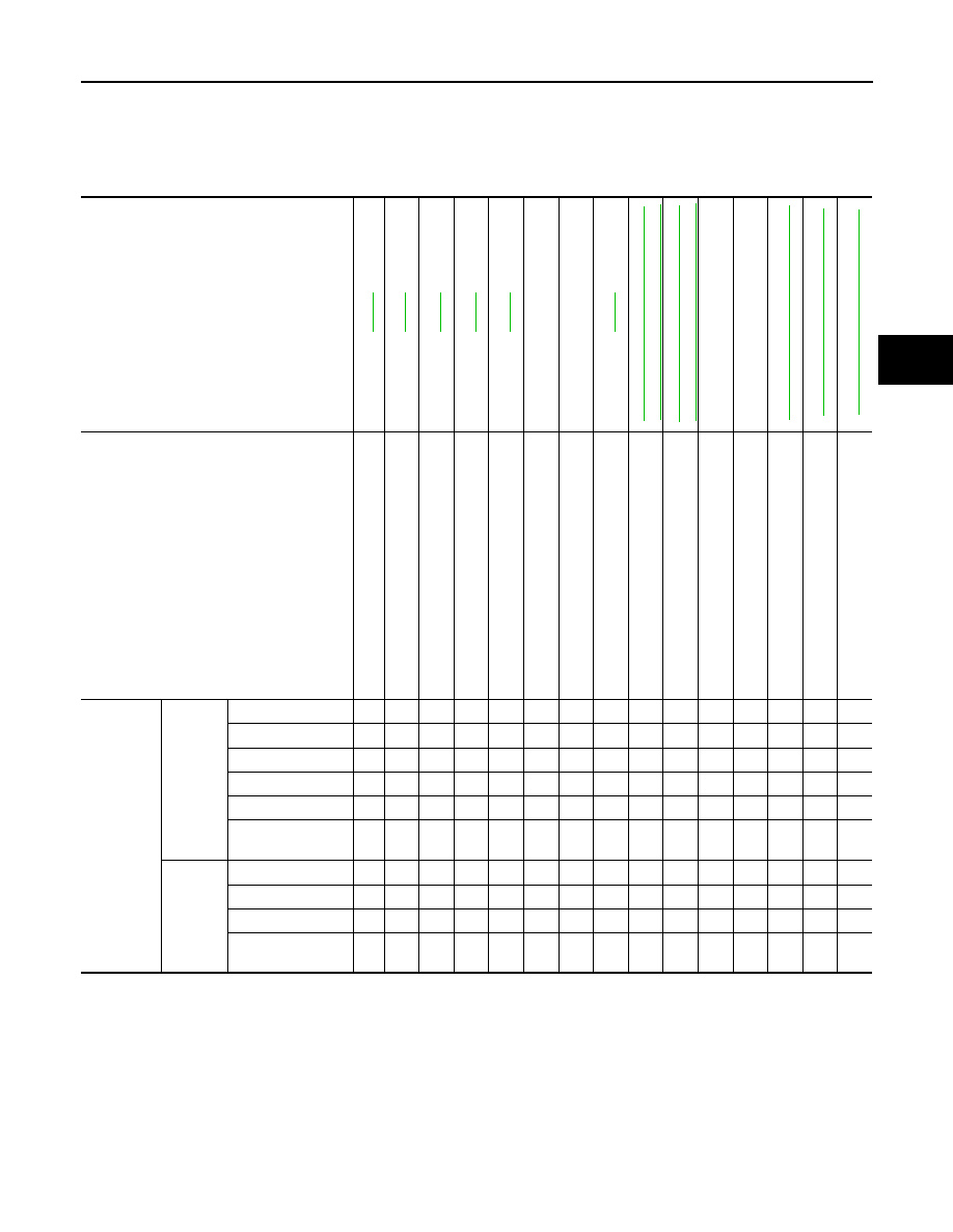
NVH Troubleshooting Chart

INFOID:0000000004212526

Use chart below to help you find the cause of the symptom. If necessary, repair or replace these parts.

×: Applicable

Reference page

WT

-60

WT

-60

WT

-60

WT

-66

WT

-60

WT

-66

F

AX-2,

 "

NVH T

ro

ub

les

ho

ot

ing

 Ch

art

"

,

FSU-2, "

NVH T

rou

ble

sh

oo

tin

g Ch

art

"

RAX

-2, "

NVH T

rou

bl

es

ho

oti

ng

 Cha

rt

"

,

RSU-2, "

NVH T

rou

bl

es

ho

ot

in

g Cha

rt

"

Refe

r to

 TI

RE

S in

 th

is chart

.

Re

fer to 

ROAD 

W

H

EEL in thi

s ch

art.

FAX-2, "

NV

H T

rou

bl

es

ho

oti

ng

 Cha

rt

"

BR-6, "

NVH T

rou

bl

es

ho

ot

in

g Cha

rt

"

ST

-2, "

NV

H T

rou

ble

shoo

ting

 Cha

rt

"

Possible cause and SUSPECTED PARTS

Im

pr

op

er i

n

st

al

la

tio

n

, lo

os

en

es

s

O

ut

-of-ro

un

d

Im

ba

la

nc

e

Incorrect t

ire 

pressure

Uneven tire 

wear

Def

orm

ati

on

 or 

da

ma

ge

No

n-u

n

iformi

ty

Incorrect t

ire 

size

FRONT A

X

LE 

AND FRONT SUSP

ENSION

REAR A

X

LE 

AND REAR SUSPE

NSION

TI

RE

S

ROAD WHEE

LS

DRIVE SHAFT

BRAKE

STE

E

RING

Symptom

TIRES

Noise

×

×

×

×

×

×

×

×

×

×

×

×

×

Shake

×

×

×

×

×

×

×

×

×

×

×

×

×

Vibration

×

×

×

×

×

×

Shimmy

×

×

×

×

×

×

×

×

×

×

×

×

×

Shudder

×

×

×

×

×

×

×

×

×

×

×

×

Poor quality ride or 
handling

×

×

×

×

×

×

×

×

×

×

ROAD 
WHEEL

Noise

×

×

×

×

×

×

×

×

×

×

Shake

×

×

×

×

×

×

×

×

×

×

Shimmy, Shudder

×

×

×

×

×

×

×

×

×

Poor quality ride or 
handling

×

×

×

×

×

×

×

WT-58

< PRECAUTION >

PRECAUTIONS

PRECAUTION

PRECAUTIONS

Precaution for Supplemental Restraint System (SRS) "AIR BAG" and "SEAT BELT 
PRE-TENSIONER"

INFOID:0000000004212527

The Supplemental Restraint System such as “AIR BAG” and “SEAT BELT PRE-TENSIONER”, used along

with a front seat belt, helps to reduce the risk or severity of injury to the driver and front passenger for certain

types of collision. This system includes seat belt switch inputs and dual stage front air bag modules. The SRS

system uses the seat belt switches to determine the front air bag deployment, and may only deploy one front

air bag, depending on the severity of a collision and whether the front occupants are belted or unbelted.

Information necessary to service the system safely is included in the SR and SB section of this Service Man-

ual.

WARNING:

• To avoid rendering the SRS inoperative, which could increase the risk of personal injury or death in

the event of a collision which would result in air bag inflation, all maintenance must be performed by

an authorized NISSAN/INFINITI dealer.

• Improper maintenance, including incorrect removal and installation of the SRS, can lead to personal

injury caused by unintentional activation of the system. For removal of Spiral Cable and Air Bag

Module, see the SR section.

• Do not use electrical test equipment on any circuit related to the SRS unless instructed to in this

Service Manual. SRS wiring harnesses can be identified by yellow and/or orange harnesses or har-

ness connectors.

Necessary for Steering Wheel Rotation After Battery Disconnect

INFOID:0000000004501286

NOTE:

• Before removing and installing any control units, first turn the push-button ignition switch to the LOCK posi-

tion, then disconnect both 12-volt battery cables.

• After finishing work, confirm that all control unit connectors are connected properly, then re-connect both 12-

volt battery cables.

• Always use CONSULT-III to perform self-diagnosis as a part of each function inspection after finishing work.

If a DTC is detected, perform trouble diagnosis according to self-diagnosis results.

This vehicle is equipped with a push-button ignition switch and a steering lock unit.

If the 12-volt battery is disconnected or discharged, the steering wheel will lock and cannot be turned.

If turning the steering wheel is required with the 12-volt battery disconnected or discharged, follow the proce-

dure below before starting the repair operation.

OPERATION PROCEDURE

1. Connect both 12-volt battery cables.

NOTE:

Supply power using jumper cables if 12-volt battery is discharged.

2. Carry the Intelligent Key or insert it to the key slot and turn the push-button ignition switch to ACC position.

(At this time, the steering lock will be released.)

3. Disconnect both 12-volt battery cables. The steering lock will remain released with both 12-volt battery

cables disconnected and the steering wheel can be turned.

4. Perform the necessary repair operation.
5. When the repair work is completed, re-connect both 12-volt battery cables. With the brake pedal released,

turn the push-button ignition switch from ACC position to ON position, then to LOCK position. (The steer-

ing wheel will lock when the push-button ignition switch is turned to LOCK position.)

6. Perform self-diagnosis check of all control units using CONSULT-III.

Precaution for work

INFOID:0000000004212528

• After removing and installing the opening/closing parts, be sure to carry out fitting adjustments to check their

operation.

• Check the lubrication level, damage, and wear of each part. If necessary, grease or replace it.

PREPARATION

WT-59

< PREPARATION >

C

D

F

G

H

I

J

K

L

M

A

B

WT

N

O

P

PREPARATION

PREPARATION

Special Service Tool

INFOID:0000000004212529

The actual shapes of Kent-Moore tools may differ from those of special service tools illustrated here.

Commercial Service Tools

INFOID:0000000004212530

Tool number 
(Kent-Moore No.)
Tool name

Description

KV991B1000
(J-45295)
Transmitter activation tool

• Transmitter wake up operation
• ID registration procedure

WEIA0144E

Tool name

Description

Power tool

Loosening bolts and nuts

PBIC0190E

WT-60

< ON-VEHICLE MAINTENANCE >

ROAD WHEEL

ON-VEHICLE MAINTENANCE

ROAD WHEEL

Inspection

INFOID:0000000004212531

1. Check tires for wear and improper inflation.
2. Check wheels for deformation, cracks and other damage. If deformed, remove wheel and check wheel

runout.

a. Remove tire from aluminum wheel and mount on a tire balance machine.
b. Set dial indicator as shown in the figure.

Wheel runout (Dial indicator value)

: Refer to 

WT-66

.

SFA975B


Content   ..  1121  1122  1123  1124   ..