Content .. 1075 1076 1077 1078 ..
Nissan Altima HL32 Hybrid. Manual - part 1077
TM-26
< ON-VEHICLE MAINTENANCE >
[HYBRID TRANSAXLE: RE0F01H]
SHIFT POSITION
SHIFT POSITION
Inspection and Adjustment
INFOID:0000000004212384
INSPECTION
1. Place selector lever in “P” position, and turn ignition switch ON (engine stop).
2. Make sure that selector lever can be shifted to other than “P” position when brake pedal is depressed.
Also make sure that selector lever can be shifted from “P” position only when brake pedal is depressed.
3. Move the selector lever and check for excessive effort, sticking, noise or rattle.
4. Confirm the selector lever stops at each position with the feel of engagement when it is moved through all
the positions. Check that the actual position of the selector lever matches the position shown by the shift
position indicator and the manual lever on the transaxle.
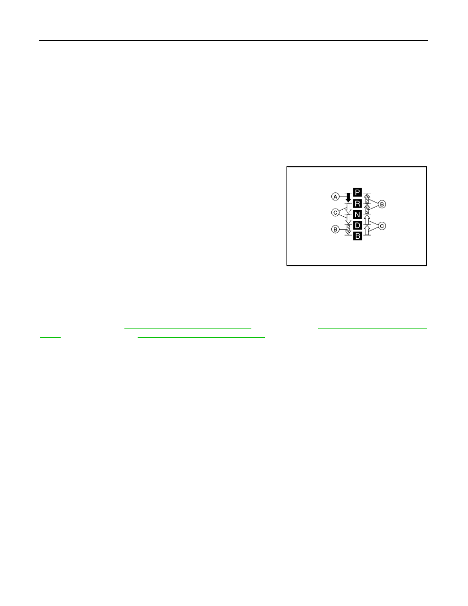
5. The method of operating the selector lever to individual posi-
tions correctly should be as shown.
• (A): Press selector button to operate selector lever, while
depressing the brake pedal.
• (B): Press selector button to operate selector lever.
• (C): Selector lever can be operated without pressing selector
button.
6. Press the selector button in the “P”, “R”, and “N” positions with-
out applying forward/backward force to selector lever, check but-
ton operation for sticking.
7. Confirm the back-up lamps illuminate only when selector lever is
placed in the “R” position. Confirm the back-up lamps do not illu-
minate when the selector lever is pushed toward the “R” position when in the “P” or “N” position.
8. Confirm the hybrid system can only be started with the selector lever in the “P” position.
9. Make sure transaxle is locked completely in “P” position.
ADJUSTMENT
For adjustment, refer to
TM-28, "Inspection and Adjustment"
TM-30, "Inspection and Adjust-
for control cable and
TM-33, "Inspection and Adjustment"
for PNP switch.
ALDIA0058GB