Nissan Altima HL32 Hybrid. Manual - part 15


  Index      Nissan     Nissan Altima HL32 Hybrid (2009 year) - Service and Repair Manual


Search            


Content   ..  13  14  15  16   ..


Nissan Altima HL32 Hybrid. Manual - part 15


AV-52

< ON-VEHICLE REPAIR >

[BASE AUDIO]

AUDIO ANTENNA

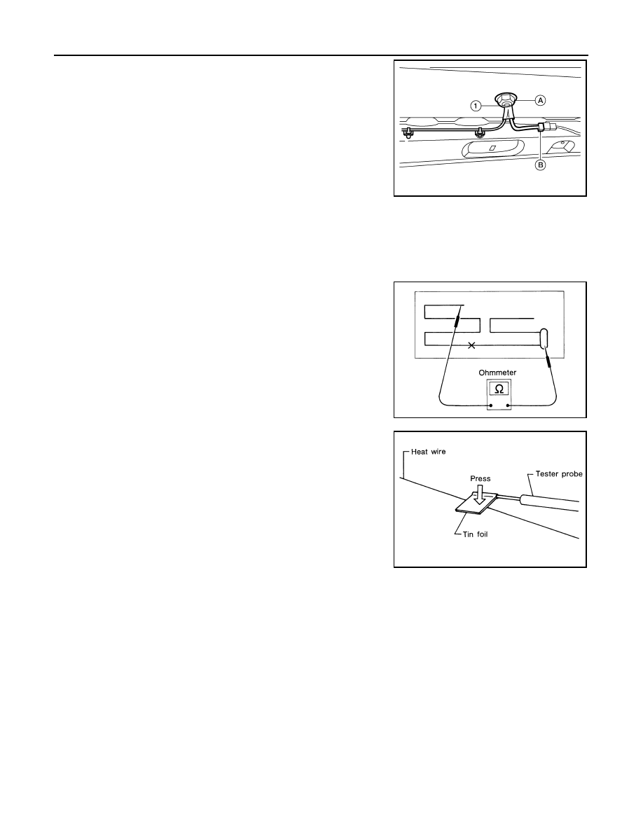
4. Remove the roof antenna nut (A), then disconnect the antenna

feeder connector (B) and remove the antenna feeder (1) from

the roof.

5. Detach the antenna feeder harness wire clips, then disconnect

the antenna feeder harness wire end and feed the antenna

feeder harness through the roof to remove the roof antenna

base.

Installation

Installation is in the reverse order of removal.

Window Antenna Repair

INFOID:0000000004219423

ELEMENT CHECK

1. Attach probe circuit tester (ohm setting) to antenna terminal on

each side.

• When measuring continuity, wrap tin foil around the top of

probe. Then, press the foil against the wire with your finger.

ALNIA0127ZZ

SEL250I

SEL122R

AV

AUDIO ANTENNA

AV-53

< ON-VEHICLE REPAIR >

[BASE AUDIO]

C

D

E

F

G

H

I

J

K

L

M

B

A

O

P

2. If an element is broken, no continuity will exist.

3. To locate a break, move probe along element. Tester indication

will change abruptly when probe passes the broken point.

REPAIR EQUIPMENT

• Conductive silver composition (DuPont No. 4817 or equivalent)

• Ruler 30 cm (11.8 in) long

• Drawing pen

• Heat gun

• Alcohol

• Cloth

REPAIRING PROCEDURE

1. Wipe broken heat wire and its surrounding area clean with a

cloth dampened in alcohol.

2. Apply a small amount of conductive silver composition to tip of

drawing pen.

Shake silver composition container before use.

3. Place ruler on glass along broken line. Deposit conductive silver

composition on break with drawing pen. Slightly overlap existing

heat wire on both sides [preferably 5 mm (0.20 in)] of the break.

SEL252I

SEL253I

PIIA0215E

AV-54

< ON-VEHICLE REPAIR >

[BASE AUDIO]

AUDIO ANTENNA

4. After repair has been completed, check repaired wire for conti-

nuity. This check should be conducted 10 minutes after silver

composition is deposited.

Do not touch repaired area while test is being conducted.

5. Apply a constant stream of hot air directly to the repaired area

for approximately 20 minutes with a heat gun. A minimum dis-

tance of 3 cm (1.2 in) should be kept between repaired area and

hot air outlet.

If a heat gun is not available, let the repaired area dry for 24

hours.

SEL012D

SEL013D

AV

STEERING SWITCH

AV-55

< ON-VEHICLE REPAIR >

[BASE AUDIO]

C

D

E

F

G

H

I

J

K

L

M

B

A

O

P

STEERING SWITCH

Removal and Installation

INFOID:0000000004219424

REMOVAL

1. Remove the driver airbag module. Refer to 

SRS-5, "Removal and Installation"

.

2. Remove the steering wheel switch assembly screws (A), then

remove the steering wheel switches (1).

INSTALLATION

Installation is in the reverse order of removal.

ALNIA0045ZZ


Content   ..  13  14  15  16   ..