Nissan Altima HL32 Hybrid. Manual - part 12
AV-40
< ECU DIAGNOSIS >
[BASE AUDIO]
SATELLITE RADIO TUNER
30
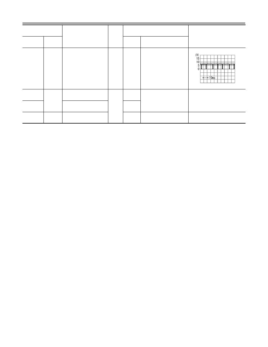
(B)
Ground
Communication signal
(AUDIO-SAT)
Input
ON
Set to the satellite radio
mode
32
(Y/R)
Ground
Battery power supply
Input
OFF
−
Battery voltage
36
(GR/W)
ACC power supply
ACC
37
(B)
–
Antenna signal
–
–
–
Terminal
(Wire color)
Item
Signal
input/
output
Condition
Voltage
(approx.)
+
–
Ignition
switch
Operation
SKIB3826E