Nissan Frontier. Manual - part 833


  Index      Nissan     Nissan Frontier (2014 year) - Service and Repair Manual


Search            


Content   ..  831  832  833  834   ..


Nissan Frontier. Manual - part 833


2014

QUICK REFERENCE GUIDE: FRONTIER

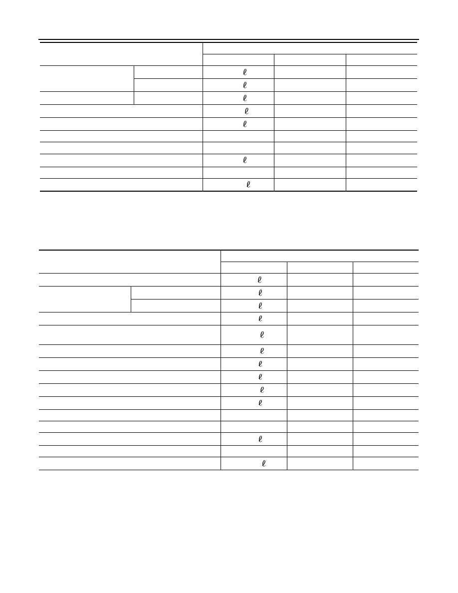
FOR MEXICO : Fluids and Lubricants

INFOID:0000000010288604

VQ40DE

Rear final drive oil

C200

1.6 

3-3/8 pt

2-7/8 pt

M226

2.0 

4-1/4 pt

3-1/2 pt

Transfer fluid

TX15B

2.0 

2-1/8 qt

1-3/4 qt

Front final drive oil

0.85 

1-3/4 pt

1-1/2 pt

Power steering fluid (PSF)

1.0 

2-1/8 pt

1-3/4 pt

Brake and clutch fluid

Multi-purpose grease

Windshield washer fluid

4.5 

1-1/4 gal

1 gal

A/C system refrigerant

0.70 

± 0.05 kg

1.54 

± 0.11 lb

1.54 

± 0.11 lb

A/C system oil

180 m

6.1 fl oz

6.3 fl oz

Description

Capacity (Approximate)

Metric

US measure

Imp measure

Description

Capacity (Approximate)

Metric

US measure

Imp measure

Fuel

80 

21-1/8 gal

17-5/8 gal

Engine oil
Drain and refill

With oil filter change

5.1 

5-3/8 qt

4-1/2 qt

Without oil filter change

4.8 

5-1/8 qt

4-1/4 qt

Dry engine (engine overhaul)

6.3 

 6-5/8 qt

5-1/2 qt

Cooling system
(with reservoir at “MAX” level)

10.2 

10-3/4 qt

9 qt

Automatic transmission fluid (ATF)

10.3 

10-7/8 qt

9-1/8 qt

Rear final drive oil

2.0 

4-1/4 pt

3-1/2 pt

Transfer fluid

2.0 

2-1/8 qt

1-3/4 qt

Front final drive oil

0.85 

1-3/4 pt

1-1/2 pt

Power steering fluid (PSF)

1.0 

2-1/8 pt

1-3/4 pt

Brake fluid

Multi-purpose grease

Windshield washer fluid

4.5 

1 1/4 gal

1 gal

A/C system refrigerant

0.70 

± 0.05 kg

1.54 

± 0.11 lb

1.54 

± 0.11 lb

A/C system oil

180 m

6.1 fl oz

6.3 fl oz

GI-1

GENERAL INFORMATION

C

D

E

F

G

H

I

J

K

L

M

B

GI

SECTION 

GI

N

O

P

CONTENTS

GENERAL INFORMATION

HOW TO USE THIS MANUAL ......................

3

HOW TO USE THIS MANUAL  ............................

3

Description ................................................................

3

Terms ........................................................................

3

Units ..........................................................................

3

Contents ....................................................................

3

Relation between Illustrations and Descriptions  .......

4

Component ................................................................

4

HOW TO FOLLOW TROUBLE DIAGNOSES .....

6

Description ................................................................

6

How to Follow Test Groups in Trouble Diagnosis ......

6

Key to Symbols Signifying Measurements or Pro-
cedures ...................................................................
..

7

HOW TO READ WIRING DIAGRAMS  ................

9

Connector symbols  ...................................................

9

Sample/wiring diagram -example- ...........................

10

Description ..............................................................

11

ABBREVIATIONS ..............................................

13

Abbreviation List ......................................................

13

TIGHTENING TORQUE OF STANDARD 
BOLTS ................................................................

18

Description ..............................................................

18

Tightening Torque Table (New Standard Includ-
ed) ...........................................................................

18

RECOMMENDED CHEMICAL PRODUCTS 
AND SEALANTS ................................................

21

Recommended Chemical Products and Sealants ....

21

VEHICLE INFORMATION ............................

22

IDENTIFICATION INFORMATION .....................

22

Model Variation  .......................................................

22

Identification Number  ..............................................

24

Dimensions .............................................................

26

Wheels & Tires ........................................................

27

PRECAUTION ..............................................

28

PRECAUTIONS .................................................

28

Description ...............................................................

28

Precaution for Supplemental Restraint System 
(SRS) "AIR BAG" and "SEAT BELT PRE-TEN-
SIONER" .................................................................

28

Precaution for NATS (NISSAN ANTI-THEFT 
SYSTEM) .................................................................

28

Cautions in Removing Battery Terminal and AV 
Control Unit ..............................................................

29

General Precautions ................................................

29

Three Way Catalyst  .................................................

30

Fuel (Regular Unleaded Gasoline Recommend-
ed) QR25DE and VQ40DE ......................................

31

Multiport Fuel Injection System or Engine Control 
System .....................................................................

31

Hoses ......................................................................

31

Engine Oils  ..............................................................

32

Air Conditioning  .......................................................

32

LIFTING POINT .................................................

33

Pantograph Jack ......................................................

33

Garage Jack and Safety Stand ................................

33

2-Pole Lift  ................................................................

33

TOW TRUCK TOWING  .....................................

35

Tow Truck Towing  ...................................................

35

Vehicle Recovery (Freeing a stuck vehicle)  ............

36

WIRING DIAGRAM ......................................

37

CONSULT CHECKING SYSTEM  .....................

37

Wiring Diagram ........................................................

37

BASIC INSPECTION  ...................................

38

SERVICE INFORMATION FOR ELECTRICAL 
INCIDENT ..........................................................

38

Work Flow ................................................................

38

Control Units and Electrical Parts ............................

38

How to Check Terminal  ...........................................

39

HOW TO USE THIS MANUAL

GI-3

< HOW TO USE THIS MANUAL >

C

D

E

F

G

H

I

J

K

L

M

B

GI

N

O

P

HOW TO USE THIS MANUAL

HOW TO USE THIS MANUAL

Description

INFOID:0000000009480194

This volume explains “Removal, Disassembly, Installation, Inspection and Adjustment” and “Trouble Diag-

noses”.

Terms

INFOID:0000000009480195

• The captions WARNING and CAUTION warn you of steps that must be followed to prevent personal injury

and/or damage to some part of the vehicle.

WARNING indicates the possibility of personal injury if instructions are not followed.

CAUTION indicates the possibility of component damage if instructions are not followed.

BOLD TYPED STATEMENTS except WARNING and CAUTION give you helpful information.

Standard value: Tolerance at inspection and adjustment.

Limit value: The maximum or minimum limit value that should not be exceeded at inspection and adjust-

ment.

Units

INFOID:0000000009480196

• The UNITS given in this manual are primarily expressed as the SI UNIT (International System of Unit), and

alternatively expressed in the metric system and in the yard/pound system.

Also with regard to tightening torque of bolts and nuts, there are descriptions both about range and about the

standard tightening torque.

“Example”

Range

Standard

Contents

INFOID:0000000009480197

• A QUICK REFERENCE INDEX, a black tab (e.g. 

) is provided on the first page. You can quickly find the

first page of each section by matching it to the section's black tab.

• THE CONTENTS are listed on the first page of each section.

• THE TITLE is indicated on the upper portion of each page and shows the part or system.

• THE PAGE NUMBER of each section consists of two or three letters which designate the particular section

and a number (e.g. “BR-5”).

• THE SMALL ILLUSTRATIONS show the important steps such as inspection, use of special tools, knacks of

work and hidden or tricky steps which are not shown in the previous large illustrations.

Assembly, inspection and adjustment procedures for the complicated units such as the automatic transaxle

or transmission, etc. are presented in a step-by-step format where necessary.

Outer Socket Lock Nut

: 59 - 78 N·m (6.0 - 8.0 kg-m, 43 - 58 ft-lb)

Drive Shaft Installation Bolt : 44.3 N·m (4.5 kg-m, 33 ft-lb)


Content   ..  831  832  833  834   ..