Nissan Frontier. Manual - part 817


  Index      Nissan     Nissan Frontier (2014 year) - Service and Repair Manual


Search            


Content   ..  815  816  817  818   ..


Nissan Frontier. Manual - part 817


WHEEL HUB

FAX-5

< PERIODIC MAINTENANCE >

C

E

F

G

H

I

J

K

L

M

A

B

FAX

N

O

P

PERIODIC MAINTENANCE

WHEEL HUB

On-Vehicle Inspection and Service

INFOID:0000000009480028

Make sure the mounting conditions (looseness, backlash) of each component and component status (wear,

damage) are normal.

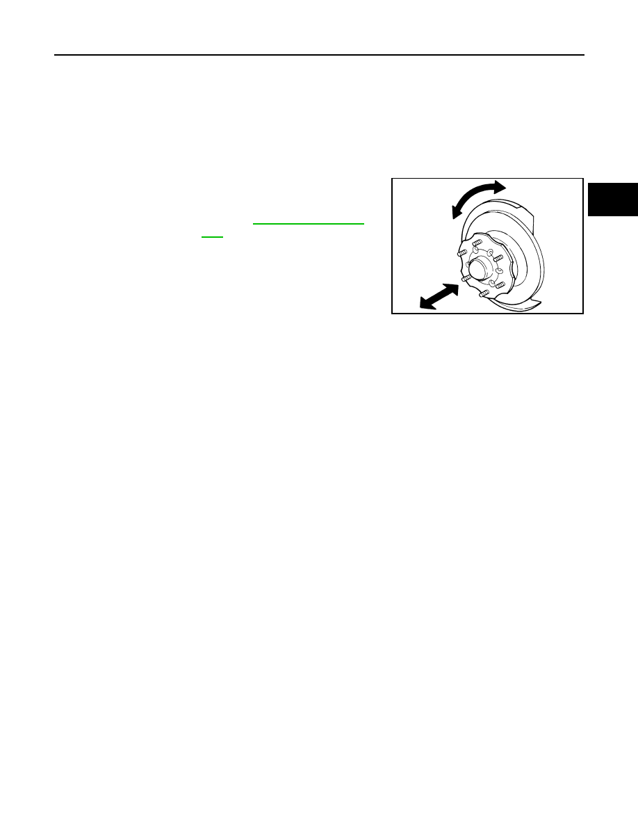
WHEEL BEARING INSPECTION

• Move wheel hub in the axial direction by hand. Make sure there is

no looseness of wheel bearing.

• Rotate wheel hub and make sure there is no unusual noise or

other irregular conditions. If there are any irregular conditions,

replace wheel hub and bearing assembly.

Axial end play limit  : Refer to 

FAX-16, "Wheel Bear-

ing"

.

SMA571A

FAX-6

< UNIT REMOVAL AND INSTALLATION >

DRIVE SHAFT

UNIT REMOVAL AND INSTALLATION

DRIVE SHAFT

Removal and Installation

INFOID:0000000009480029

REMOVAL 

1. Remove wheel and tire using power tool. Refer to 

WT-48, "Adjustment"

.

2. Remove engine under cover using power tool. Refer to 

EXT-15, "Removal and Installation"

.

3. Remove wheel sensor harness from mount on knuckle, then disconnect wheel sensor harness connector.

CAUTION:

Do not pull on wheel sensor harness.

4. Remove wheel hub and bearing assembly. Refer to 

FAX-8, "Removal and Installation"

.

• It is not necessary to remove wheel sensor from wheel hub when wheel hub is not being replaced.

• Carefully feed wheel sensor harness through hole in splash shield.

5. Separate upper link ball joint stud from steering knuckle using

Tool.

• Support lower link with jack.

6. Remove drive shaft assembly.

• Pry drive shaft front final drive using suitable tool.

• Remove differential side oil seal. Refer to 

DLN-189, "Removal

and Installation"

.

INSPECTION AFTER REMOVAL

• Move joint up, down, left, right, and in axial direction. Check for any rough movement or significant loose-

ness.

• Check boot for cracks or other damage, and for grease leakage.

• If damaged, disassemble drive shaft to verify damage, and repair

or replace as necessary.

INSTALLATION

Installation is in the reverse order of removal.

1.

Differential side oil seal

2.

Drive shaft

3.

Drive shaft lock nut

4.

Cotter pin

WDIA0341E

Tool number

: ST29020001 (J-24319-01)

WEIA0119E

SFA108A

DRIVE SHAFT

FAX-7

< UNIT REMOVAL AND INSTALLATION >

C

E

F

G

H

I

J

K

L

M

A

B

FAX

N

O

P

• When installing drive shaft onto front final drive, use Tool to pre-

vent damage to the oil seal while inserting drive shaft. Slide drive

shaft sliding joint and tap with a hammer to install securely.

CAUTION:

Do not reuse the differential side oil seal.

• Tighten wheel nuts to specification. Refer to 

WT-48, "Adjustment"

.

Tool number

: KV38105500 (J-33904)

SDIA2615E

FAX-8

< UNIT REMOVAL AND INSTALLATION >

WHEEL HUB

WHEEL HUB

Removal and Installation

INFOID:0000000009480030

REMOVAL

1. Remove wheel and tire using power tool. Refer to 

WT-48, "Adjustment"

.

2. Without disassembling the hydraulic lines, remove caliper torque member bolts using power tool. Then

reposition brake caliper aside with wire. Refer to 

BR-35, "Removal and Installation of Brake Caliper and

Disc Rotor"

.

CAUTION:

Do not press brake pedal while brake caliper is removed.

3. Put alignment mark on disc rotor and wheel hub and bearing

assembly, then remove disc rotor.

4. On models with 4WD, remove cotter pin, then remove lock nut from drive shaft using power tool. Refer to

FAX-6, "Removal and Installation"

.

5. Remove wheel sensor from wheel hub and bearing assembly. Refer to 

BRC-113, "Removal and Installa-

tion"

 (Type 1), 

BRC-234, "Removal and Installation"

 (Type 2).

• Inspect the wheel sensor O-ring, replace the wheel sensor assembly if damaged.

• Clean the wheel sensor hole and mounting surface with a suitable brake cleaner and clean lint-free

shop rag. Be careful that dirt and debris does not enter the axle bearing area.

• Apply a coat of suitable grease to the wheel sensor O-ring and mounting hole.

CAUTION:

Do not pull on the wheel sensor harness.

6. On models with 4WD, separate drive shaft from wheel hub and bearing assembly.
7. Remove wheel hub and bearing assembly bolts using power tool.
8. Remove splash guard and wheel hub and bearing assembly from steering knuckle.

1.

Disc rotor

2.

Wheel hub and bearing assembly

3.

Wheel stud

4.

Splash guard

5.

Steering knuckle

6.

Wheel sensor bracket

WDIA0228E

WDIA0044E


Content   ..  815  816  817  818   ..