Nissan Frontier. Manual - part 643


  Index      Nissan     Nissan Frontier (2014 year) - Service and Repair Manual


Search            


Content   ..  641  642  643  644   ..


Nissan Frontier. Manual - part 643


P0133, P0153 A/F SENSOR 1

EC-1143

< DTC/CIRCUIT DIAGNOSIS >

[VQ40DE FOR MEXICO]

C

D

E

F

G

H

I

J

K

L

M

A

EC

N

P

O

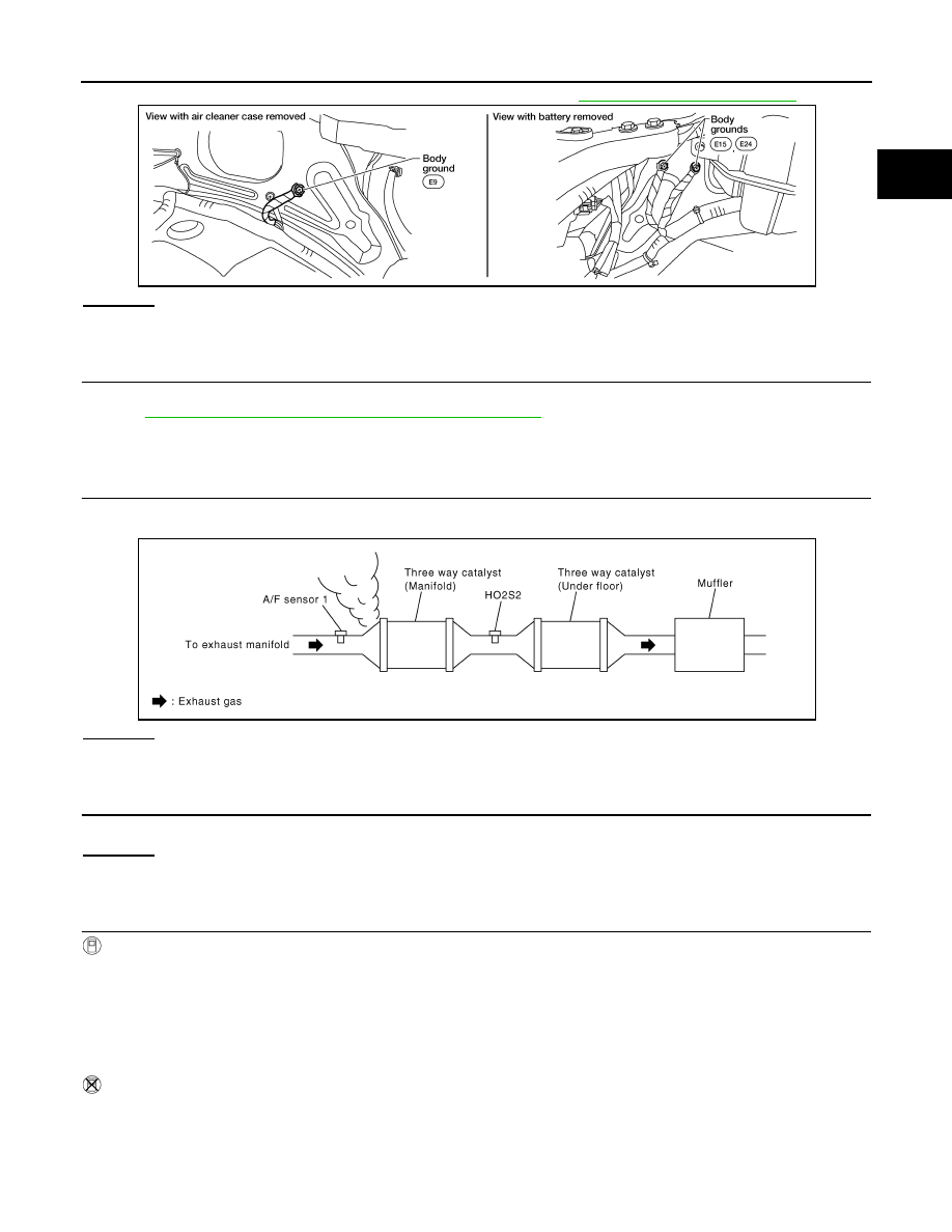
2. Loosen and retighten three ground screws on the body. Refer to 

EC-1094, "Ground Inspection"

.

OK or NG

OK

>> GO TO 2.

NG

>> Repair or replace ground connections.

2.

RETIGHTEN AIR FUEL RATIO (A/F) SENSOR 1

Loosen and retighten A/F sensor 1.

Refer to 

EM-148, "Removal and Installation (Exhaust Manifold)"

.

>> GO TO 3.

3.

CHECK EXHAUST GAS LEAK

1. Start engine and run it at idle.

2. Listen for an exhaust gas leak before three way catalyst (manifold).

OK or NG

OK

>> GO TO 4.

NG

>> Repair or replace.

4.

CHECK FOR INTAKE AIR LEAK

Listen for an intake air leak after the mass air flow sensor.
OK or NG

OK

>> GO TO 5.

NG

>> Repair or replace.

5.

CLEAR THE SELF-LEARNING DATA

 With CONSULT

1. Start engine and warm it up to normal operating temperature.

2. Select “SELF-LEARNING CONT” in “WORK SUPPORT” mode with CONSULT.

3. Clear the self-learning control coefficient by touching “CLEAR” or “START”.

4. Run engine for at least 10 minutes at idle speed.

Is the 1st trip DTC P0171, P172, P0174 or P0175 detected? Is it difficult to start engine?

 Without CONSULT

1. Start engine and warm it up to normal operating temperature.

2. Turn ignition switch OFF.

BBIA0539E

PBIB1216E

EC-1144

< DTC/CIRCUIT DIAGNOSIS >

[VQ40DE FOR MEXICO]

P0133, P0153 A/F SENSOR 1

3. Disconnect mass air flow sensor harness connector.

4. Restart engine and let it idle for at least 3 seconds.

5. Stop engine and reconnect mass air flow sensor harness con-

nector.

6. Check DTC P0102 is displayed.

7. Erase the DTC memory. Refer to 

EC-1005, "On Board Diagno-

sis Function"

 (Without CONSULT) or 

EC-1008, "CONSULT

Function"

 (With CONSULT).

8. Check DTC P0000 is displayed.

9. Run engine for at least 10 minutes at idle speed.

Is the 1st trip DTC P0171, P0172, P0174 or P0175 detected?

Is it difficult to start engine?

Yes or No

Yes

>> Perform trouble diagnosis for DTC P0171, P0174 or P0172, P0175. Refer to 

EC-1167

 or 

EC-

1173

.

No

>> GO TO 6.

6.

CHECK A/F SENSOR 1 POWER SUPPLY CIRCUIT

1. Turn ignition switch OFF.

2. Disconnect A/F sensor 1 harness connector.

3. Turn ignition switch ON.

4. Check voltage between A/F sensor 1 terminal 4 and ground with

CONSULT or tester.

OK or NG

OK

>> GO TO 8.

NG

>> GO TO 7.

7.

DETECT MALFUNCTIONING PART

Check the following.

• Harness connectors E2, F32

• IPDM E/R connector E119

• 15 A fuse (No.54)

• Harness for open or short between A/F sensor 1 and fuse

>> Repair or replace harness or connectors.

8.

CHECK A/F SENSOR 1 INPUT SIGNAL CIRCUIT FOR OPEN AND SHORT

1. Turn ignition switch OFF.

2. Disconnect ECM harness connector.

3. Check harness continuity between A/F sensor 1 terminal and ECM terminal as follows.

Refer to Wiring Diagram.

BBIA0541E

Voltage: Battery voltage

BBIA0544E

PBIB3308E

P0133, P0153 A/F SENSOR 1

EC-1145

< DTC/CIRCUIT DIAGNOSIS >

[VQ40DE FOR MEXICO]

C

D

E

F

G

H

I

J

K

L

M

A

EC

N

P

O

4. Check harness continuity between the following terminals and ground.

Refer to Wiring Diagram.

5. Also check harness for short to power.
OK or NG

OK

>> GO TO 9.

NG

>> Repair open circuit or short to ground or short to power in harness or connectors.

9.

CHECK A/F SENSOR 1 HEATER

Refer to 

EC-1102, "Component Inspection"

.

OK or NG

OK

>> GO TO 10.

NG

>> GO TO 13.

10.

CHECK MASS AIR FLOW SENSOR

Refer to 

EC-1112, "Component Inspection"

.

OK or NG

OK

>> GO TO 11. 

NG

>> Replace mass air flow sensor. Refer to 

EM-141, "Exploded View"

.

11.

CHECK PCV VALVE

Refer to 

EC-1364, "Component Inspection"

.

OK or NG

OK

>> GO TO 12.

NG

>> Repair or replace PCV valve. Refer to 

EM-158, "Exploded View"

.

12.

CHECK INTERMITTENT INCIDENT

Perfor

GI-42, "Intermittent Incident"

.

OK or NG

OK

>> GO TO 13.

NG

>> Repair or replace.

13.

REPLACE A/F SENSOR 1

Replace malfunctioning A/F sensor 1. Refer to 

EM-147, "Exploded View"

.

CAUTION:

• Discard any A/F sensor which has been dropped from a height of more than 0.5 m (19.7 in) onto a

hard surface such as a concrete floor; use a new one.

• Before installing new A/F sensor, clean exhaust system threads using Heated Oxygen Sensor

Thread Cleaner tool J-43897-18 or J-43897-12 and approved anti-seize lubricant.

A/F sensor 1 terminal

ECM terminal

Bank1

1

35

2

56

Bank 2

1

16

2

75

Continuity should exist.

Bank 1

Bank 2

A/F sensor 1 terminal

ECM terminal

A/F sensor 1 terminal

ECM terminal

1

35

1

16

2

56

2

75

Continuity should not exist.

EC-1146

< DTC/CIRCUIT DIAGNOSIS >

[VQ40DE FOR MEXICO]

P0133, P0153 A/F SENSOR 1

>> INSPECTION END


Content   ..  641  642  643  644   ..