Nissan Frontier. Manual - part 318


  Index      Nissan     Nissan Frontier (2014 year) - Service and Repair Manual


Search            


Content   ..  316  317  318  319   ..


Nissan Frontier. Manual - part 318


DLN-174

< UNIT REMOVAL AND INSTALLATION >

[PROPELLER SHAFT: 3S1330-2BJ100]

REAR PROPELLER SHAFT

UNIT REMOVAL AND INSTALLATION

REAR PROPELLER SHAFT

Removal and Installation

INFOID:0000000009479764
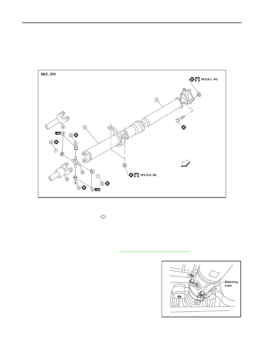
COMPONENTS

Model 3S1330–2BJ100

NOTE:

When removing components such as hoses, tubes/lines, etc., cap or plug openings to prevent fluid from spill-

ing.

REMOVAL

1. Remove under cover (if equipped). Refer to 

EXT-15, "Removal and Installation"

.

2. Put the transmission in neutral and release the parking brake.
3. Put matching marks on the rear propeller shaft flange yoke and

the rear final drive companion flange as shown. 

CAUTION:

For matching marks, use paint. Do not damage the rear pro-

peller shaft flange yoke or the companion flange.

4. Remove the bolts, then remove the propeller shaft from the rear

final drive and transmission or transfer.

INSPECTION 

AWDIA0689GB

1.

Propeller shaft (1st shaft)

2.

Snap ring

3.

Journal bearing

4.

Sleeve yoke (4WD)

5.

Sleeve yoke (2WD) 

6.

Journal

7.

Propeller shaft (2nd shaft)

Front

WDIA0049E

REAR PROPELLER SHAFT

DLN-175

< UNIT REMOVAL AND INSTALLATION >

[PROPELLER SHAFT: 3S1330-2BJ100]

C

E

F

G

H

I

J

K

L

M

A

B

DLN

N

O

P

• Inspect the propeller shaft runout. If runout exceeds the limit,

replace the propeller shaft assembly. 

• While holding the flange yoke on one side, check axial play of the

joint as shown. If the journal axial play exceeds the specification,

repair or replace the journal parts. 

• Check the propeller shaft for dents or cracks. If damage is

detected, replace the propeller shaft assembly.

INSTALLATION

Installation is in the reverse order of removal.

• After installation, check for vibration by driving the vehicle. Refer to 

DLN-172, "NVH Troubleshooting Chart"

.

CAUTION:

Do not reuse the bolts and nuts. Always install new ones.

Propeller shaft runout limit
2WD : Refer to 

DLN-179, "General 

Specification"

4WD : Refer to 

DLN-179, "General 

Specification"

LDIA0121E

Journal axial play  : Refer to 

DLN-179, "General Spec-

ification"

LDIA0117E

DLN-176

< UNIT DISASSEMBLY AND ASSEMBLY >

[PROPELLER SHAFT: 3S1330-2BJ100]

REAR PROPELLER SHAFT

UNIT DISASSEMBLY AND ASSEMBLY

REAR PROPELLER SHAFT

Disassembly and Assembly

INFOID:0000000009479765

DISASSEMBLY

Journal

1. Remove the propeller shaft assembly from the vehicle. Refer to 

DLN-174, "Removal and Installation"

.

2. Put matching marks on the rear propeller shaft tube and flange

yoke as shown.

CAUTION:

For matching marks use paint. Do not damage the rear pro-

peller shaft or flange yoke.

3. Remove the snap rings.

CAUTION:

Do not reuse snap rings.

4. Push out and remove the journal bearing by lightly tapping the

yoke with a hammer, taking care not to damage the journal or

yoke hole.

5. Remove the bearing at the opposite side of above operation. 

NOTE:

Put marks on the disassembled parts so that they can be rein-

stalled in their original positions from which they were removed.

SPD128

APD011

SPD732

SPD131

REAR PROPELLER SHAFT

DLN-177

< UNIT DISASSEMBLY AND ASSEMBLY >

[PROPELLER SHAFT: 3S1330-2BJ100]

C

E

F

G

H

I

J

K

L

M

A

B

DLN

N

O

P

Center Support Bearing

1. Remove the propeller shaft assembly from the vehicle. Refer to 

DLN-174, "Removal and Installation"

.

2. Put matching marks on the propeller shaft tube and the slip yoke.

CAUTION:

For matching marks, use paint. Do not damage the propeller shaft tube or slip yoke.

3. Remove and discard the clamp near the center support bearing, then slide the slip yoke off of propeller

shaft tube.

4. Press the center support bearing off the propeller shaft tube

using Tool and suitable hydraulic press.

ASSEMBLY

Journal

1. Assemble the journal bearings. Apply multipurpose grease on

the bearing inner surface.

NOTE:

During assembly, use caution so that the needle bearings do not

fall down.

2. Select snap rings that will provide the specified play in an axial

direction of the journal, and install them. Refer to 

DLN-179,

"Snap Ring"

.

CAUTION:

Do not reuse snap rings.

NOTE:

Select snap rings with a difference in thickness at both sides

within 0.02 mm (0.0008 in).

3. Adjust the thrust clearance between the bearing and snap ring

to zero by tapping the yoke.

Tool number

: 205-D002

LDIA0152E

WPD019

APD012

SPD732


Content   ..  316  317  318  319   ..