Nissan Frontier. Manual - part 316


  Index      Nissan     Nissan Frontier (2014 year) - Service and Repair Manual


Search            


Content   ..  314  315  316  317   ..


Nissan Frontier. Manual - part 316


DLN-166

< UNIT DISASSEMBLY AND ASSEMBLY >

[3S1330]

REAR PROPELLER SHAFT

Center Support Bearing

1. Remove the propeller shaft assembly from the vehicle. Refer to 

DLN-163, "Removal and Installation"

.

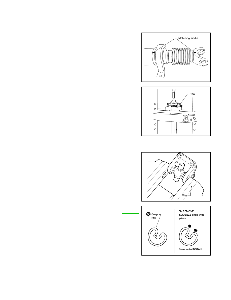
2. Put matching marks on the propeller shaft tube and the slip

yoke.

CAUTION:

For matching marks, use paint. Do not damage the propel-

ler shaft tube or slip yoke.

3. Remove and discard the clamp near the center support bearing,

then slide the slip yoke off of propeller shaft tube.

4. Press the center support bearing off the propeller shaft tube

using Tool and suitable hydraulic press.

ASSEMBLY

Journal

1. Assemble the journal bearings. Apply multipurpose grease on

the bearing inner surface.

NOTE:

During assembly, use caution so that the needle bearings do not

fall down.

2. Select snap rings that will provide the specified play in an axial

direction of the journal, and install them. Refer to 

DLN-169,

"Snap Ring"

.

CAUTION:

Do not reuse snap rings.

NOTE:

Select snap rings with a difference in thickness at both sides

within 0.02 mm (0.0008 in).

LDIA0151E

Tool number

: 205-D002

LDIA0152E

WPD019

APD012

REAR PROPELLER SHAFT

DLN-167

< UNIT DISASSEMBLY AND ASSEMBLY >

[3S1330]

C

E

F

G

H

I

J

K

L

M

A

B

DLN

N

O

P

3. Adjust the thrust clearance between the bearing and snap ring

to zero by tapping the yoke.

4. Make sure that the journal moves smoothly and is below the

joint flex effort specification. Refer to 

DLN-169, "General Specifi-

cation"

.

Center Support Bearing

1. Apply a thin coat of multi-purpose grease to both the propeller shaft tube and the inside surface of the

center support bearing.

2. Install the center support bearing on the propeller shaft tube

using a suitable pipe pressing on the inner race.

3. Install a new clamp over the boot on the slip yoke. 
4. Align the matching marks and install the slip yoke on the propel-

ler shaft tube. 

5. Clean the surfaces and position the boot over the propeller shaft tube and tighten the clamp.

SPD732

LDIA0119E

LDIA0153E

LDIA0151E

DLN-168

< UNIT DISASSEMBLY AND ASSEMBLY >

[3S1330]

REAR PROPELLER SHAFT

6. Install the center support bearing bracket, then install the rear

propeller shaft assembly in the vehicle. Refer to 

DLN-163,

"Removal and Installation"

.

WDIA0066E

SERVICE DATA AND SPECIFICATIONS (SDS)

DLN-169

< SERVICE DATA AND SPECIFICATIONS (SDS) 

[3S1330]

C

E

F

G

H

I

J

K

L

M

A

B

DLN

N

O

P

SERVICE DATA AND SPECIFICATIONS (SDS)

SERVICE DATA AND SPECIFICATIONS (SDS)

General Specification

INFOID:0000000009479757

Snap Ring

INFOID:0000000009479758

Unit: mm (in)

*: Always check with the Parts Department for the latest parts information.

Applied model

VQ40DE

2WD

M/T short bed

A/T long bed

Propeller shaft model

3S1330

3

Flange type
Sleeve type

Number of joints

Coupling method with rear final drive

Coupling method with transmission

1st Shaft length (Center bearing to spider) 

674.5 

± 1.5 mm (26.56 ± 0.06 in)

741.5 

± 1.5 mm (29.19 ± 0.06 in)

2nd Shaft length (Spider to spider)

783.8 

± 1.5 mm (30.86 ± 0.06 in)

1152.8 

± 1.5 mm (45.39 ± 0.06 in)

Shaft outer diameter

76.2 + 0.00/ - 0.13 mm (3.00 + 0.00/ - 0.01 in)

0.02 mm (0.0008 in) or less

0.6 mm (0.024 in) or less

2.26 N·m (0.23 kg-m, 20 in-lb) or less

Journal axial play

Propeller shaft runout limit

Propeller shaft joint flex effort

Thickness

Color

Part Number*

1.99 (0.0783)

White

37146-C9400

 2.02 (0.0795)

Yellow

37147-C9400

2.05 (0.0807)

Red

37148-C9400

2.08 (0.0819)

Green

37149-C9400

2.11 (0.0831)

Blue

37150-C9400

2.14 (0.0843)

Light brown

37151-C9400

2.17 (0.0854)

Black

37152-C9400

2.20 (0.0866)

No paint

37153-C9400


Content   ..  314  315  316  317   ..