Nissan Frontier. Manual - part 319


  Index      Nissan     Nissan Frontier (2014 year) - Service and Repair Manual


Search            


Content   ..  317  318  319  320   ..


Nissan Frontier. Manual - part 319


DLN-178

< UNIT DISASSEMBLY AND ASSEMBLY >

[PROPELLER SHAFT: 3S1330-2BJ100]

REAR PROPELLER SHAFT

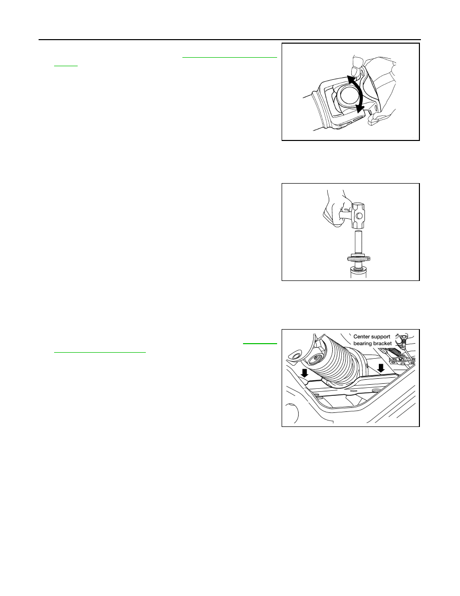
4. Make sure that the journal moves smoothly and is below the

joint flex effort specification. Refer to 

DLN-179, "General Specifi-

cation"

.

Center Support Bearing

1. Apply a thin coat of multi-purpose grease to both the propeller shaft tube and the inside surface of the

center support bearing.

2. Install the center support bearing on the propeller shaft tube

using a suitable pipe pressing on the inner race.

3. Install a new clamp over the boot on the slip yoke. 
4. Align the matching marks and install the slip yoke on the propeller shaft tube. 

5. Clean the surfaces and position the boot over the propeller shaft tube and tighten the clamp.
6. Install the center support bearing bracket, then install the rear

propeller shaft assembly in the vehicle. Refer to 

DLN-174,

"Removal and Installation"

.

LDIA0119E

LDIA0153E

WDIA0066E

SERVICE DATA AND SPECIFICATIONS (SDS)

DLN-179

< SERVICE DATA AND SPECIFICATIONS (SDS) 

[PROPELLER SHAFT: 3S1330-2BJ100]

C

E

F

G

H

I

J

K

L

M

A

B

DLN

N

O

P

SERVICE DATA AND SPECIFICATIONS (SDS)

SERVICE DATA AND SPECIFICATIONS (SDS)

General Specification

INFOID:0000000009479766

*Off-Road

Snap Ring

INFOID:0000000009479767

Model 3S1330–2B100

Unit: mm (in)

*: Always check with the Parts Department for the latest parts information.

Applied model

Long bed 4WD

Short bed 2WD

VQ40DE

A/T

A/T

Propeller shaft model

3S1330–2BJ100

Number of joints

3

Coupling method with rear final drive

Flange type

Coupling method with transmission

Sleeve type

1st Shaft length (Center bearing to spider) 

625.5 

± 1.5 mm (24.63 ± 0.06 in)

741.5 

± 1.5 mm (29.19 ± 0.06 in)

2nd Shaft length (CV joint to flange mount surface)

813.6 

± 1.5 mm (32.03 ± 0.06 in)

813.6 

± 1.5 mm (32.03 ± 0.06 in) 

[783.6 

± 1.5 mm (30.85 ± 0.06 in)]*

Shaft outer diameter

76.2 +0.00/ - 0.13 mm (3.00 + 0.00/ - 0.01 in)

Journal axial play

0.02 mm (0.0008 in) or less

Propeller shaft runout limit

0.6 mm (0.024 in) or less

Propeller shaft joint flex effort

2.26 N·m (0.23 kg-m, 20 in-lb) or less

Thickness

Color

Part Number*

1.99 (0.0783)

White

37146-C9400

 2.02 (0.0795)

Yellow

37147-C9400

2.05 (0.0807)

Red

37148-C9400

2.08 (0.0819)

Green

37149-C9400

2.11 (0.0831)

Blue

37150-C9400

2.14 (0.0843)

Light brown

37151-C9400

2.17 (0.0854)

Black

37152-C9400

2.20 (0.0866)

No paint

37153-C9400

DLN-180

< PRECAUTION >

[FRONT FINAL DRIVE: R180A]

PRECAUTIONS

PRECAUTION

PRECAUTIONS

Precaution for Supplemental Restraint System (SRS) "AIR BAG" and "SEAT BELT 
PRE-TENSIONER"

INFOID:0000000010118722

The Supplemental Restraint System such as “AIR BAG” and “SEAT BELT PRE-TENSIONER”, used along

with a front seat belt, helps to reduce the risk or severity of injury to the driver and front passenger for certain

types of collision. This system includes seat belt switch inputs and dual stage front air bag modules. The SRS

system uses the seat belt switches to determine the front air bag deployment, and may only deploy one front

air bag, depending on the severity of a collision and whether the front occupants are belted or unbelted.

Information necessary to service the system safely is included in the SR and SB section of this Service Man-

ual.

WARNING:

• To avoid rendering the SRS inoperative, which could increase the risk of personal injury or death in

the event of a collision which would result in air bag inflation, all maintenance must be performed by

an authorized NISSAN/INFINITI dealer.

• Improper maintenance, including incorrect removal and installation of the SRS, can lead to personal

injury caused by unintentional activation of the system. For removal of Spiral Cable and Air Bag

Module, see the SR section.

• Do not use electrical test equipment on any circuit related to the SRS unless instructed to in this

Service Manual. SRS wiring harnesses can be identified by yellow and/or orange harnesses or har-

ness connectors.

PRECAUTIONS WHEN USING POWER TOOLS (AIR OR ELECTRIC) AND HAMMERS

WARNING:

• When working near the Airbag Diagnosis Sensor Unit or other Airbag System sensors with the Igni-

tion ON or engine running, DO NOT use air or electric power tools or strike near the sensor(s) with a

hammer. Heavy vibration could activate the sensor(s) and deploy the air bag(s), possibly causing

serious injury.

• When using air or electric power tools or hammers, always switch the Ignition OFF, disconnect the

battery and wait at least three minutes before performing any service.

Precaution for Servicing Front Final Drive

INFOID:0000000009479769

• Before starting diagnosis of the vehicle, understand the symptoms well. Perform correct and systematic

operations. 

• Check for the correct installation status prior to removal or disassembly. When matching marks are required,

be certain they do not interfere with the function of the parts they are applied to. 

• Overhaul should be done in a clean work area, a dust proof area is recommended.

• Before disassembly, completely remove sand and mud from the exterior of the unit, preventing them from

entering into the unit during disassembly or assembly.

• Always use shop paper for cleaning the inside of components.

• Avoid using cotton gloves or a shop cloth to prevent the entering of lint.

• Check appearance of the disassembled parts for damage, deformation, and abnormal wear. Replace them

with new ones if necessary. 

• Gaskets, seals and O-rings should be replaced any time the unit is disassembled.

• Clean and flush the parts sufficiently and blow them dry.

• Be careful not to damage sliding surfaces and mating surfaces.

• When applying sealant, remove the old sealant from the mating surface; then remove any moisture, oil, and

foreign materials from the application and mating surfaces.

• In principle, tighten nuts or bolts gradually in several steps working diagonally from inside to outside. If a

tightening sequence is specified, observe it.

• During assembly, observe the specified tightening torque.

• Add new differential gear oil, petroleum jelly, or multi-purpose grease, as specified.

PREPARATION

DLN-181

< PREPARATION >

[FRONT FINAL DRIVE: R180A]

C

E

F

G

H

I

J

K

L

M

A

B

DLN

N

O

P

PREPARATION

PREPARATION

Special Service Tool

INFOID:0000000009479770

The actual shape of the tools may differ from those illustrated here.

Tool number
(TechMate No.)
Tool name

Description

ST33290001
(J-34286)
Puller

Removing front oil seal 

ST30720000
(J-25405)
Drift

• Installing front oil seal
• Installing side oil seal
a: 77 mm (3.03 in) dia.
b: 55.5 mm (2.185 in) dia.

ST27863000
(

)

Drift

• Installing front oil seal
• Installing side oil seal
a: 74.5 mm (2.933 in) dia.
b: 62.5 mm (2.461 in) dia.

ST3127S000
(J-25765-A)
Preload gauge
1: GG91030000

(J-25765)
Torque wrench

2: HT62940000

(

)

Socket adapter (1/2

″)

3: HT62900000

(

)

Socket adapter (3/8

″)

Measuring drive pinion bearing preload torque 
and total preload torque

KV10111100
(J-37228)
Seal cutter

Removing carrier cover

ZZA0601D

ZZA0811D

ZZA1003D

NT124

S-NT046


Content   ..  317  318  319  320   ..