Nissan Frontier. Manual - part 299


  Index      Nissan     Nissan Frontier (2014 year) - Service and Repair Manual


Search            


Content   ..  297  298  299  300   ..


Nissan Frontier. Manual - part 299


DLN-98

< REMOVAL AND INSTALLATION >

[TRANSFER: TX15B]

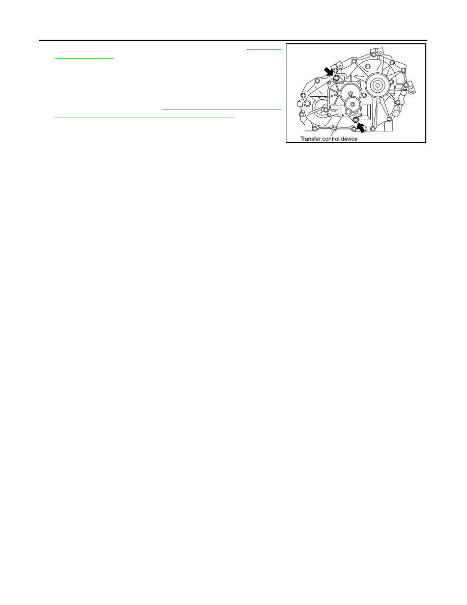
TRANSFER CONTROL DEVICE

c.

Tighten the bolts to the specified torque. Refer to 

DLN-103,

"Exploded View"

.

3. Install the breather hose to the transfer control device.
4. Connect the transfer control device connector.
5. After the installation, check the 4WD shift indicator pattern. If

NG, adjust the position between the transfer assembly and

transfer control unit. Refer to 

DLN-83, "Precaution for Transfer

Assembly and Transfer Control Unit Replacement"

.

SDIA2212E

AIR BREATHER HOSE

DLN-99

< REMOVAL AND INSTALLATION >

[TRANSFER: TX15B]

C

E

F

G

H

I

J

K

L

M

A

B

DLN

N

O

P

AIR BREATHER HOSE

Removal and Installation

INFOID:0000000009479716

COMPONENTS

REMOVAL

1. Disconnect air breather hose from transfer control device.
2. Disconnect air breather hose from breather tube (transfer).
3. Release air breather hose clamp and clips as necessary.
4. Disconnect air breather hoses from breather tube.

CAUTION:

Note paint marks for installation.

INSTALLATION

CAUTION:

Make sure there are no pinched or restricted areas on each air breather hose caused by folding or

bending when installing it.
1. Install each air breather hose into the breather tube (metal con-

nector) until the hose end reaches the end of the curved section.

Set each air breather hose with paint mark facing upward. 

1.

Breather tube

2.

Clip A

3.

Clip B

4.

Clip C

5.

Clip D

6.

Breather tube (transfer)

7.

Air breather hose clamp

8.

Transfer control device

SDIA3351E

SDIA3299E

DLN-100

< REMOVAL AND INSTALLATION >

[TRANSFER: TX15B]

AIR BREATHER HOSE

2. Install transfer control device air breather hose and transfer air

breather hose on clip A and clip B with the paint mark facing

upward.

3. Install clip C on transfer control device air breather hose and

transfer air breather hose with the paint mark matched.

4. Install transfer control device air breather hose and transfer air

breather hose on clip D with the paint mark facing upward.

5. Install transfer air breather hose (A) into the breather tube

(transfer, metal connector) until the hose end reaches the base

of the tube. Set transfer air breather hose with paint mark (B)

facing upward.

6. Install transfer control device air breather hose into transfer con-

trol device (case connector) until the hose end reaches the base

of the tube. Set transfer control device air breather hose with

paint mark facing forward.

SDIA3353E

SDIA3354E

SDIA3355E

AWDIA0784ZZ

SDIA3300E

TRANSFER ASSEMBLY

DLN-101

< UNIT REMOVAL AND INSTALLATION >

[TRANSFER: TX15B]

C

E

F

G

H

I

J

K

L

M

A

B

DLN

N

O

P

UNIT REMOVAL AND INSTALLATION

TRANSFER ASSEMBLY

Removal and Installation

INFOID:0000000009479717

NOTE:

When removing components such as hoses, tubes/lines, etc., cap or plug openings to prevent fluid from spill-

ing.

REMOVAL 

1. Switch 4WD shift switch to 2WD and set transfer assembly to 2WD.
2. Partially drain the transfer fluid. Refer to 

DLN-90, "Replacement"

.

3. Remove the transmission under cover (if equipped) using power tool.
4. Remove the center exhaust tube and main muffler. Refer to 

EX-6, "Removal and Installation"

.

5. Remove the front and rear propeller shafts. Refer to 

DLN-134, "Removal and Installation"

 (front) and 

DLN-

143, "Removal and Installation"

 (2S1330) or 

DLN-174, "Removal and Installation"

 (3S1330-2BJ100).

CAUTION:

Do not damage spline, sleeve yoke and rear oil seal when removing rear propeller shaft.

6. Remove insulator nuts from the transmission crossmember. Refer to 

TM-74, "Removal and Installation

from Vehicle (For 4WD Models)"

 (M/T) or 

TM-310, "Removal and Installation for VQ40DE 4WD Models"

(A/T).

7. Position two suitable jacks under the transmission and transfer assembly.
8. Remove the transmission crossmember. Refer to 

TM-74, "Removal and Installation from Vehicle (For

4WD Models)"

 (M/T) or 

TM-310, "Removal and Installation for VQ40DE 4WD Models"

 (A/T).

WARNING:

Support transmission and transfer assembly using two suitable jacks while removing transmis-

sion crossmember.

9. Disconnect the harness connectors from the following:

• ATP switch

• 4LO switch

• Wait detection switch

• Transfer control device

10. Remove harness from retainers.
11. Disconnect each air breather hose from the following. Refer to 

DLN-99, "Removal and Installation"

.

• Transfer control device

• Breather tube (transfer)

12. Remove the transfer to transmission and transmission to transfer bolts.

WARNING:

Support transfer assembly with suitable jack while removing it.

13. Remove the transfer assembly.

CAUTION:

Do not damage transmission rear oil seal (A/T).

INSTALLATION

Installation is in the reverse order of removal.

• Tighten the bolts to specification.

• Fill the transfer with new fluid. Refer to 

DLN-90, "Replacement"

.

• Check the transfer fluid. Refer to 

MA-47, "TRANSFER FLUID :

Inspection"

.

• Start the engine for one minute. Then stop the engine and recheck

the transfer fluid. Refer to 

MA-47, "TRANSFER FLUID : Inspec-

tion"

.

Tightening torque

: 36 N·m (3.7kg-m, 27 ft-lb)

WDIA0510E


Content   ..  297  298  299  300   ..